Design Methodology for MuGFET ESD Protection Devices

a technology of protection device and design methodology, which is applied in the testing/measurement of individual semiconductor devices, semiconductor/solid-state devices, instruments, etc., can solve the problems of high initial leakage, high complexity, and devices with too high initial leakage, etc., and achieve the effect of optimizing

Inactive Publication Date: 2009-11-12
INTERUNIVERSITAIR MICRO ELECTRONICS CENT (IMEC VZW)
View PDF0 Cites 184 Cited by
  • Summary
  • Abstract
  • Description
  • Claims
  • Application Information

AI Technical Summary

Benefits of technology

[0007]It is an aim of the present invention to provide a method for manufacturing MuGFE

Problems solved by technology

Major challenges lie ahead for the ESD design engineer.
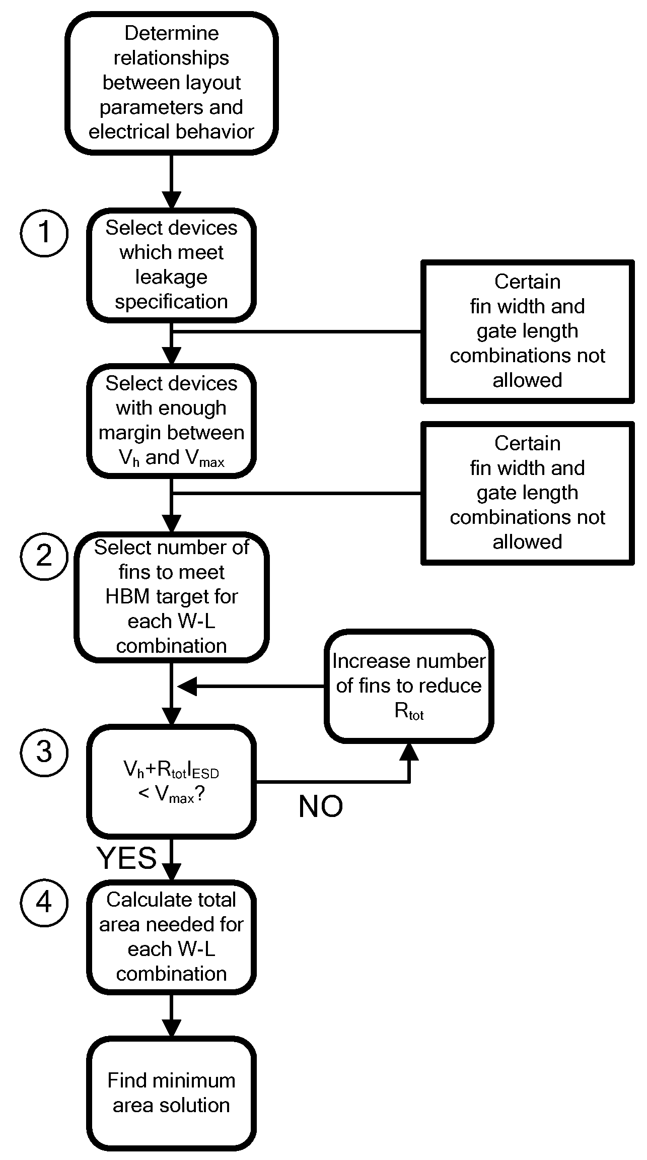
A design methodology is needed because the more complex geometry of FinFET devices compared to planar introduces a higher degree of complexity that make optimization absolutely not obvious as compared to planar devices.
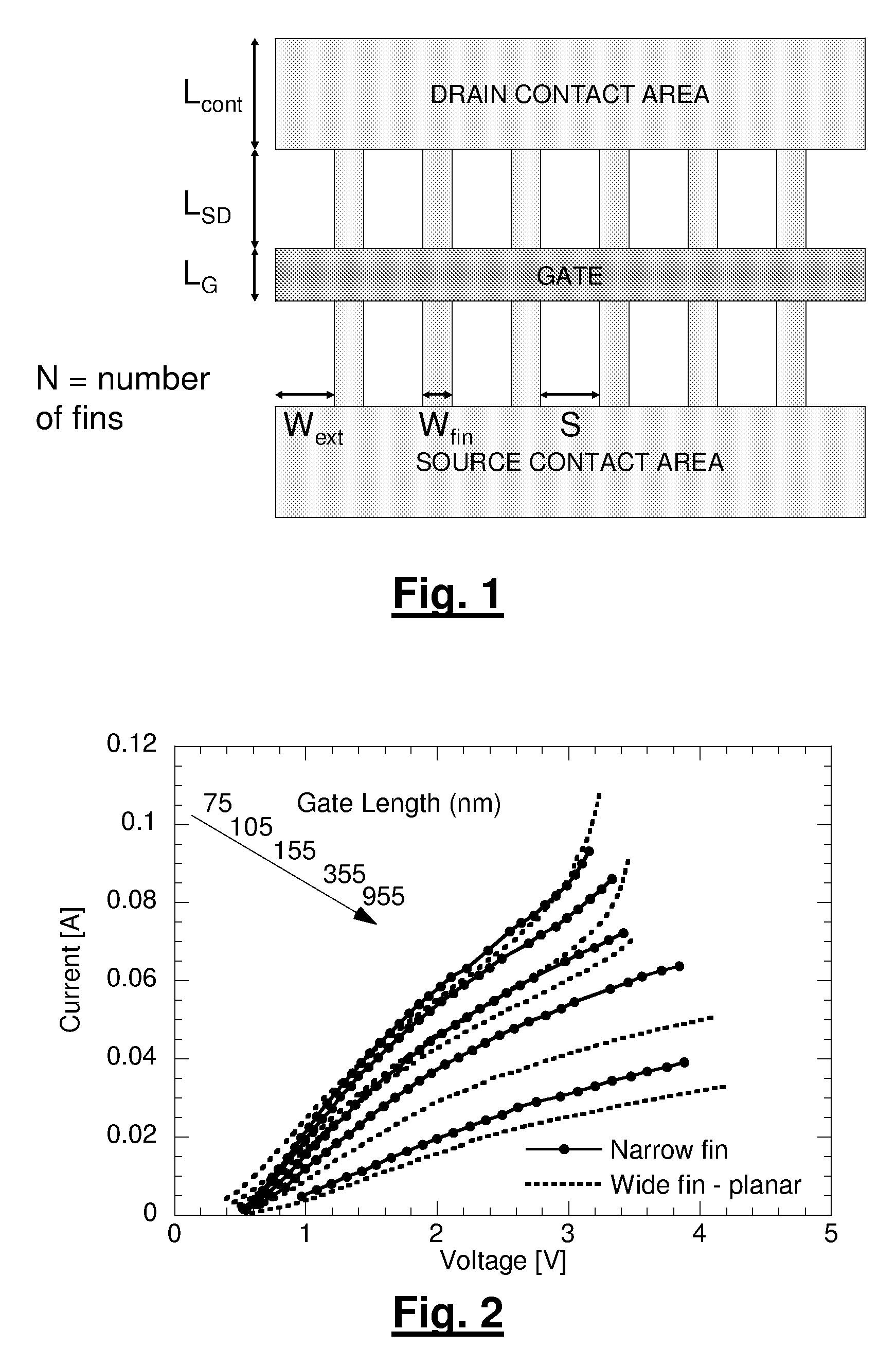
For wide fin (planar) devices (FIG. 2 dotted lines) for small gate lengths, a VT roll-off is seen because of loss of SCE control.
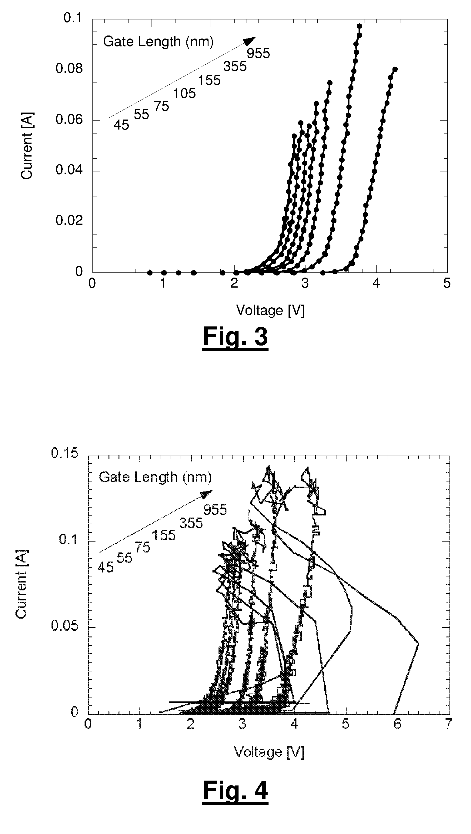
Devices with too high initial leakage would consequently have a low ESD robustness, and hence are not considered.
It2 and Ron may be impacted by constraints in the metal wiring and/or accumulative heating of folded structures.
It is clear that any LG or Wfin deviation from the optimum leads to a drastic increase in the required area.
No solutions exist for small LG because of the leakage current limitation and

Method used


Image

  • Design Methodology for MuGFET ESD Protection Devices
  • Design Methodology for MuGFET ESD Protection Devices
  • Design Methodology for MuGFET ESD Protection Devices

Examples


Embodiment Construction

[0060]The present invention will be described with respect to particular embodiments and with reference to certain drawings but the invention is not limited thereto but only by the claims. The drawings described are only schematic and are non-limiting. In the drawings, the size of some of the elements may be exaggerated and not drawn on scale for illustrative purposes. The dimensions and the relative dimensions do not necessarily correspond to actual reductions to practice of the invention.

[0061]Furthermore, the terms first, second, third and the like in the description and in the claims, are used for distinguishing between similar elements and not necessarily for describing a sequential or chronological order. The terms are interchangeable under appropriate circumstances and the embodiments of the invention can operate in other sequences than described or illustrated herein.

[0062]Moreover, the terms top, bottom, over, under and the like in the description and the claims are used fo...


PUM


Abstract

A method for manufacturing a MuGFET ESD protection device having a given layout by means of a given manufacturing process, the method comprising selecting multiple interdependent layout and process parameters of which a first set are fixed by said manufacturing process and a second set are variable, selecting multiple combinations of possible layout and process parameter values which meet predetermined ESD constraints; determining an optimum value for at least one other parameter in view of a predetermined design target apart from the predetermined ESD constraints; determining values for fin width (Wfin), gate length (LG) and number of fins (N) on the basis of the optimum value; and manufacturing said MuGFET ESD protection device using the given manufacturing and process values.

Description

CROSS-REFERENCE TO RELATED APPLICATIONS[0001]The present application claims priority to European Patent Application EP 08156029.4 filed in the EPO Patent Office on May 9, 2008, the entire contents of which is incorporated herein by reference.BACKGROUND[0002]1. Field of the Invention[0003]The present invention relates to designing and manufacturing MuGFET ESD Protection Devices.[0004]2. Description of the Related Art[0005]The FinFET transistor is the most widely studied multi-gate architecture for technology-scaling below 45 nm due to its excellent control of Short Channel Effects (SCE) and its compatibility with standard CMOS processing. In Trémouilles et al, “Understanding the Optimization of Sub-45 nm MuGFET Devices for ESD Applications”, ESD 2007, pp 408-415, a variety of ESD device parameters (failure current It2, holding voltage Vh, on-resistance Ron, leakage current and area consumption) of a Grounded-Gate-NMOS FinFET device were investigated as a function of different layout ...

Claims


Application Information

Patent Timeline
IPC IPC(8): H01L21/66
CPCH01L29/66795H01L27/0248
Inventor THIJS, STEVENLINTEN, DIMITRITREMOUILLES, DAVID ERIC
Owner INTERUNIVERSITAIR MICRO ELECTRONICS CENT (IMEC VZW)
Why Eureka
Try Eureka