
Angular velocity/angular acceleration calculator, torque estimator, and combustion state estimator

a technology of angular acceleration and calculator, which is applied in the direction of instruments, electrical control, force/torque/work measurement apparatus, etc., can solve the problems of durability and cost, the method of japanese patent application laid-open no. 2005, and the inability to calculate an angular acceleration. to achieve accurate estimation of the combustion sta

Active Publication Date: 2009-11-19
MITSUBISHI ELECTRIC CORP
View PDF6 Cites 33 Cited by
  • Summary
  • Abstract
  • Description
  • Claims
  • Application Information

AI Technical Summary

Benefits of technology

The present invention provides an angular velocity / angular acceleration calculator that accurately calculates the angular velocity and angular acceleration of a crank in an internal combustion engine using a crank angle sensor signal. Additionally, the invention includes a torque estimator that accurately estimates the gas pressure torque and external torque, and a combustion state estimator that accurately estimates the combustion state of the engine. These technical effects allow for improved engine performance and efficiency.

Problems solved by technology

However, problems on durability and cost arise in such a method of measuring an internal pressure of a cylinder with a cylinder internal pressure sensor and calculating a torque.
Therefore, this method is not for calculating an angular acceleration.
Accordingly, the method of Japanese Patent Application Laid-Open No. 2005-61371 is limitedly applicable since a gas pressure torque can be measured only in a case where an external torque excluding a friction torque is obviously equal to zero or in a case where a load torque can be estimated with an additional measurement device such as an inclination sensor.

Method used


Image

  • Angular velocity/angular acceleration calculator, torque estimator, and combustion state estimator
  • Angular velocity/angular acceleration calculator, torque estimator, and combustion state estimator
  • Angular velocity/angular acceleration calculator, torque estimator, and combustion state estimator

Examples


embodiment

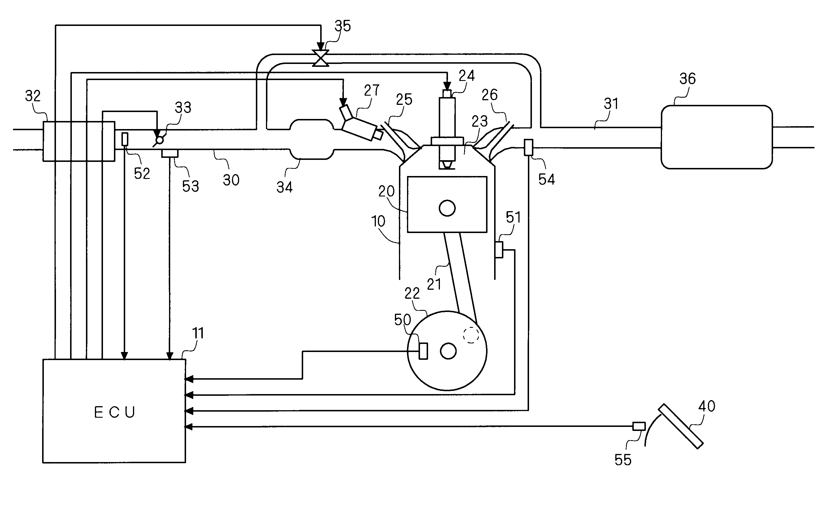
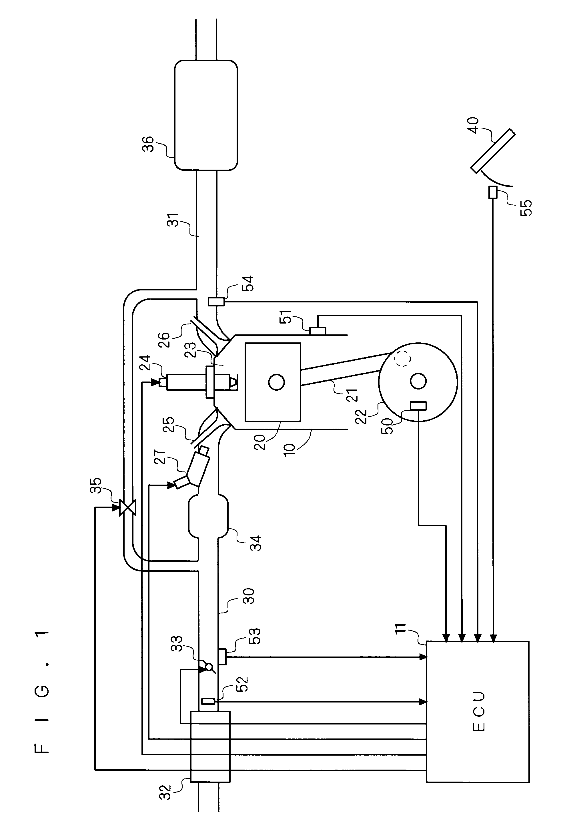
[0022]FIG. 1 is a schematic diagram of an internal combustion engine that includes a combustion state estimator according to the present embodiment. The internal combustion engine shown in FIG. 1 exemplifies a four-stroke straight four-cylinder engine. FIG. 1 shows an engine 10 that has pistons 20 respectively provided in the cylinders, and combustion chambers 23 respectively disposed above the pistons 20.

[0023]The engine 10 is connected to an intake path 30 and an exhaust path 31. Intake air passes through an air filter 32 that is provided at an upstream end of the intake path 30, and enters a surge tank 34 via an airflow sensor 52 and a throttle valve 33. Disposed in the vicinity of the throttle valve 33 is a throttle sensor 53 that detects the amount of throttle opening. The air having entered the surge tank 34 is taken into the combustion chambers 23 of the respective cylinders via intake valves 25 that are provided at a downstream end of the intake path 30. Disposed on the down...


PUM


Abstract

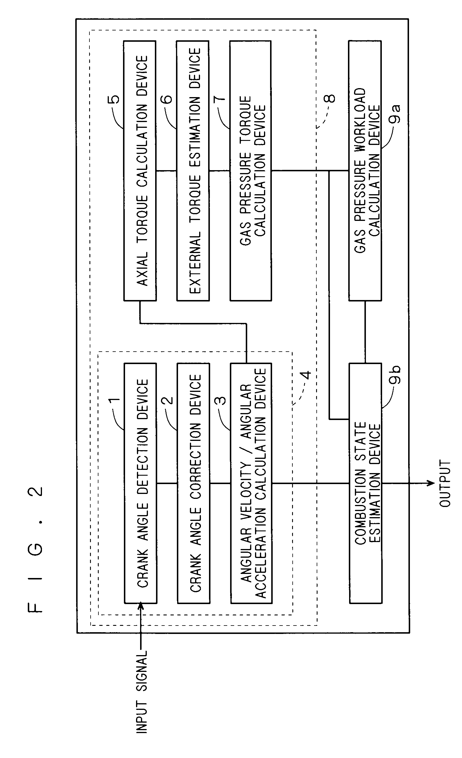
An angular velocity / angular acceleration calculator of the crankshaft in an internal combustion engine includes a crank angle detection device, a crank angle correction device, and an angular velocity / angular acceleration calculation device. The crank angle detection device detects a crank angle in the internal combustion engine and a time at the crank angle. The crank angle correction device corrects the crank angle and the time thus detected to an equiangular crank angle and a time corresponding thereto. The angular velocity / angular acceleration calculation device calculates an angular velocity and an angular acceleration of the crankshaft by converting a function of the time with respect to the crank angle that are corrected by the crank angle correction device so as to be regarded as a periodic function, and utilizing the discrete Fourier transform of the converted function.

Description

BACKGROUND OF THE INVENTION[0001]1. Field of the Invention[0002]The present invention relates to angular velocity / angular acceleration calculators, torque estimators, and combustion state estimators, and particularly relates to an angular velocity / angular acceleration calculator, a torque estimator, and a combustion state estimator for an internal combustion engine.[0003]2. Description of the Background Art[0004]Highly accurate control of an internal combustion engine is effectively realized by measuring a combustion state of the engine and controlling the engine with a measurement result thereof being fed back. For such highly accurate control, it is important to precisely measure the combustion state of the engine. The combustion state of the engine can be measured by measuring an internal pressure of a cylinder with a cylinder internal pressure sensor to calculate a torque, or by estimating a gas pressure torque according to a crank angle sensor signal.[0005]Japanese Patent Appli...

Claims


Application Information

Patent Timeline
Patent Type & Authority Applications(United States)
IPC IPC(8): G01M15/04
CPCF02D41/009F02D41/0097F02D41/1497F02D2041/1417G01P15/165F02D2200/1004F02D2200/1012G01P3/489F02D2041/288
Inventor NAGANO, TAKAFUMIIWAMOTO, TAKASHITANABE, TOMOKO
Owner MITSUBISHI ELECTRIC CORP
Learn More