

Liquid crystal display
a liquid crystal display and display technology, applied in non-linear optics, instruments, optics, etc., can solve the problems of reducing contrast performance, reducing numerical aperture of pixels, and light leakage, so as to prevent light leakage, avoid depolarization problems, and prevent depolarization
- Summary
- Abstract
- Description
- Claims
- Application Information
AI Technical Summary
Benefits of technology
Problems solved by technology
Method used
Image

Examples
Embodiment Construction
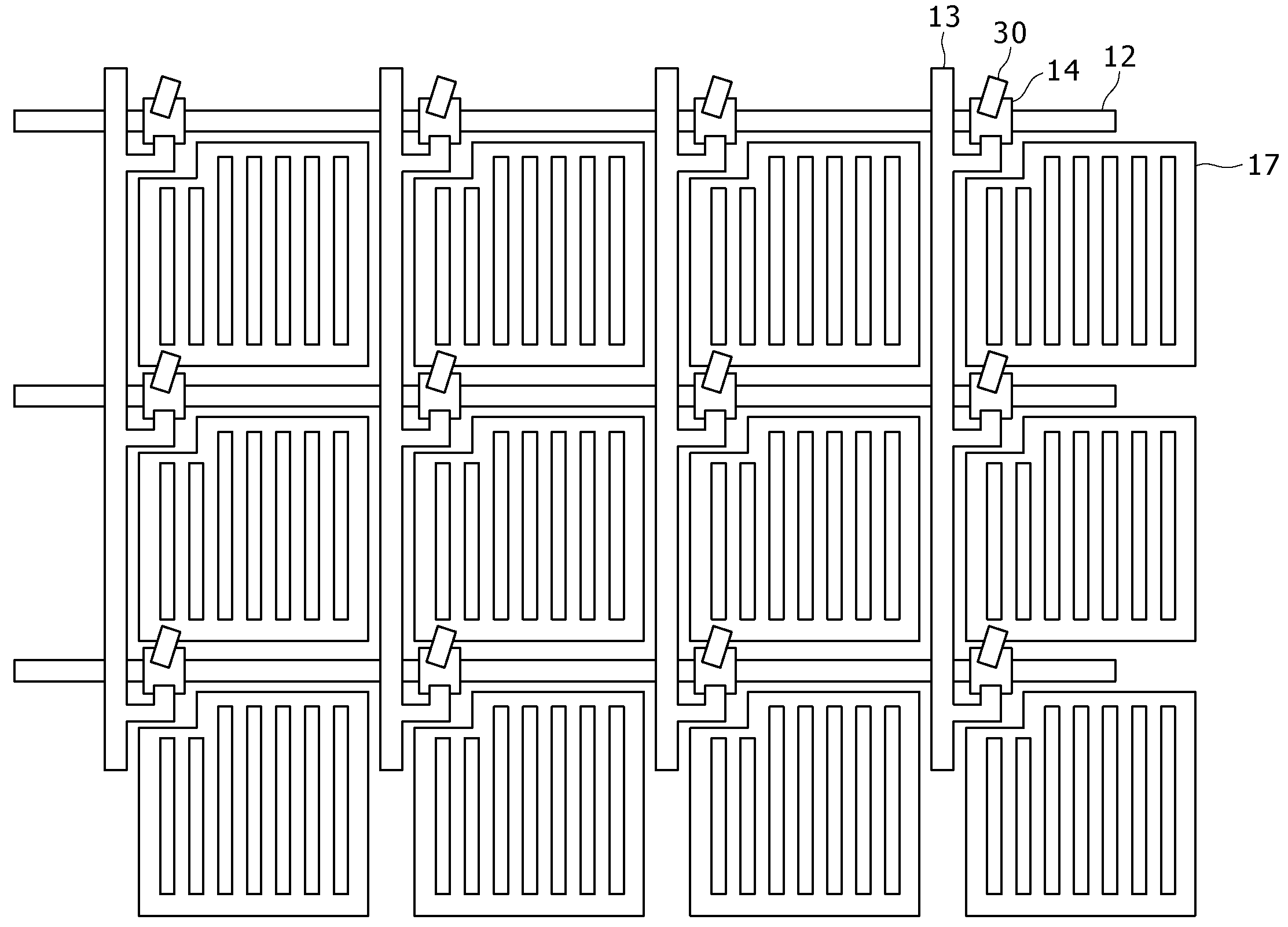
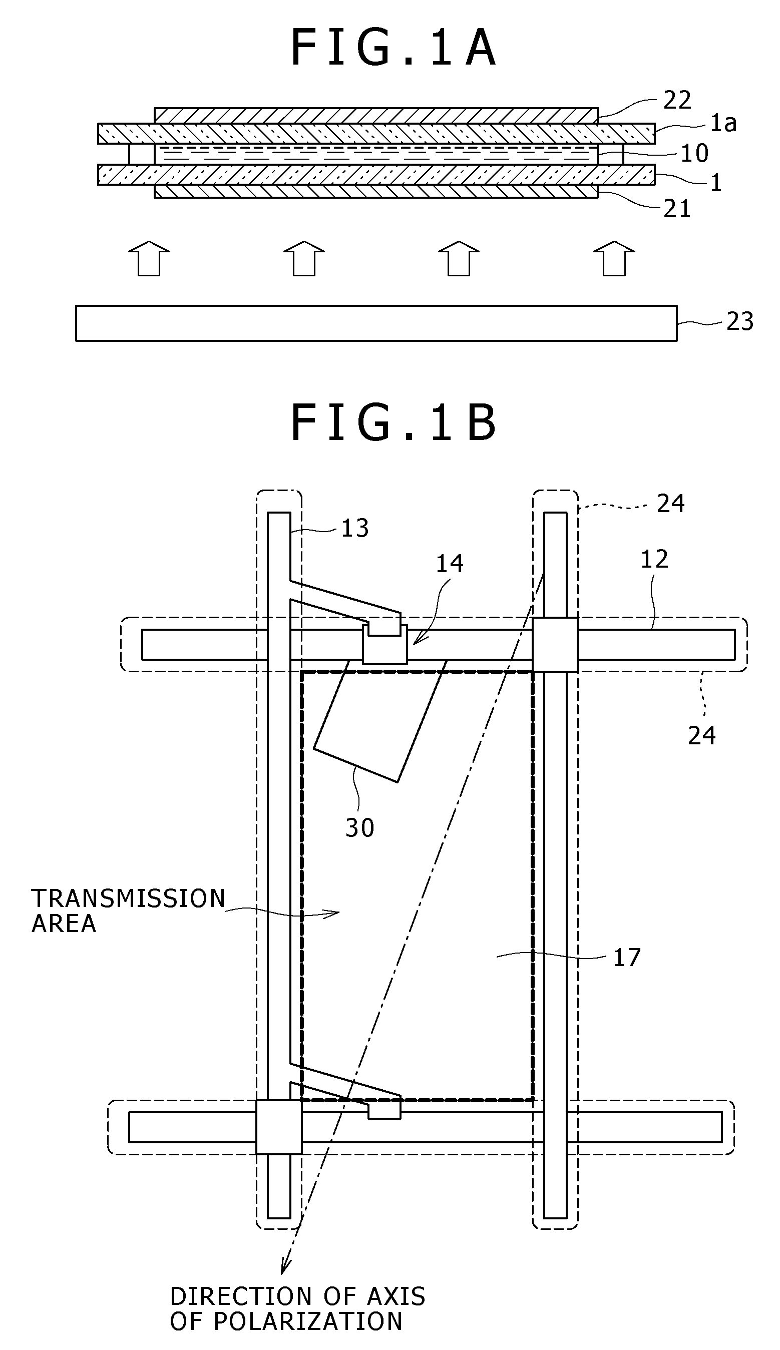
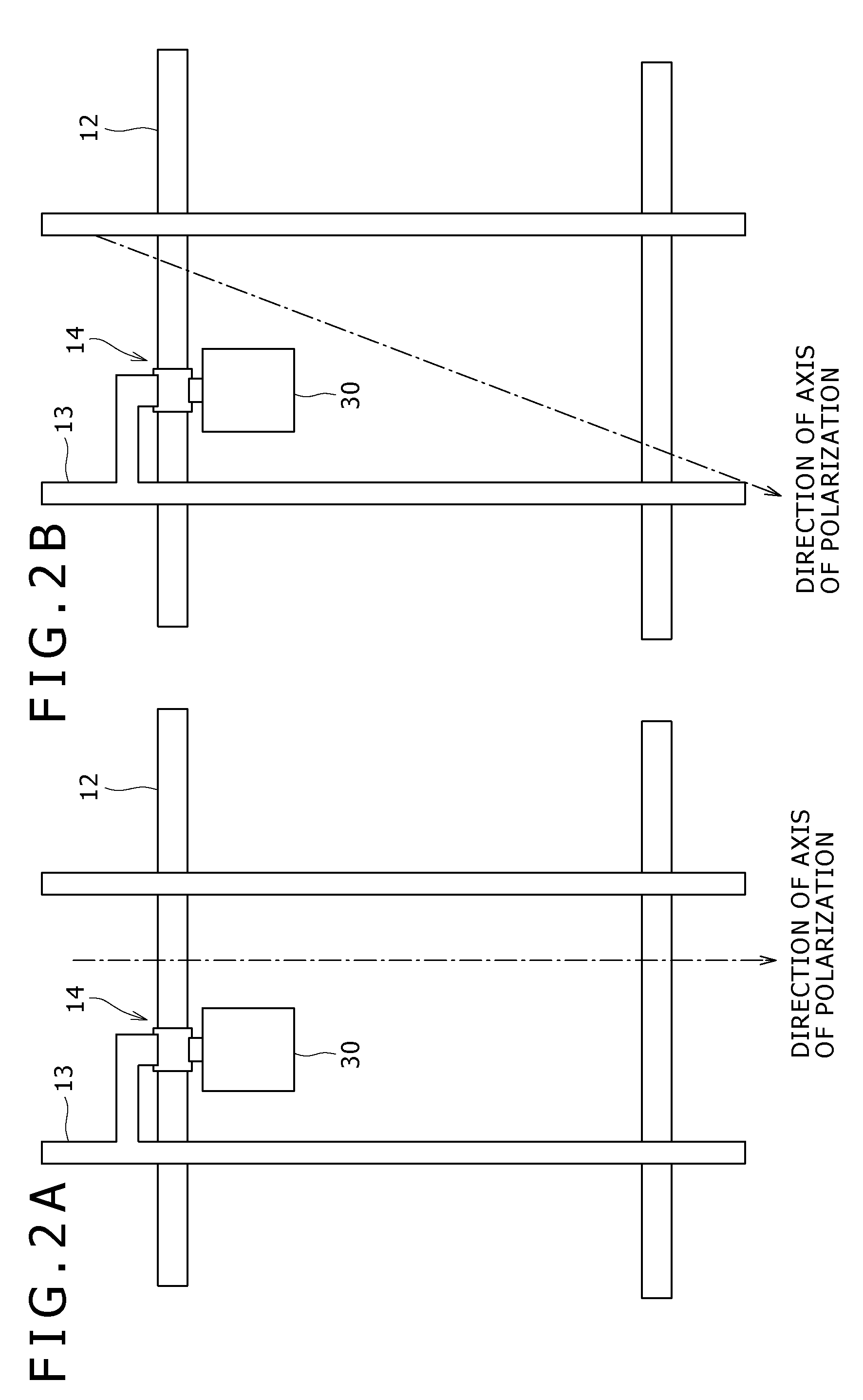
[0022]Now, embodiments of the liquid crystal display pertaining to the present invention will be described in detail below referring to the drawings. FIGS. 1A and 1B schematically illustrate a first embodiment of the liquid crystal display pertaining to the present invention, in which FIG. 1A illustrates the overall sectional structure of the liquid crystal display, and FIG. 1B is a schematic plan view of a structure corresponding to one pixel.
[0023]As shown in FIG. 1A, the liquid crystal display includes a pair of substrates 1 and la, a liquid crystal 10 held therebetween, and a polarizing plate 21 disposed on the side of one of the substrates 1. The polarizing plate 21 converts externally coming incident light into linearly polarized light. In this embodiment, the liquid crystal display is of the transmission type in which a backlight 23 is provided. The polarizing plate 21 converts illuminating light emitted from the backlight 23 into linearly polarized light. The liquid crystal ...
PUM
| Property | Measurement | Unit |
|---|---|---|
| voltage | aaaaa | aaaaa |
| transparent | aaaaa | aaaaa |
| area | aaaaa | aaaaa |
Abstract
Description
Claims
Application Information