Fuel cell system and driving method of fuel cell system

Inactive Publication Date: 2009-11-19
TOYOTA JIDOSHA KK
View PDF4 Cites 14 Cited by
  • Summary
  • Abstract
  • Description
  • Claims
  • Application Information

AI Technical Summary

Benefits of technology

[0003]At the timing of detection of the large variation of the output voltage, however, the overhydration state in the solid polymer membrane has already proceeded to an extent of starting a decrease of power generation efficiency. The detected

Problems solved by technology

At the timing of detection of the large variation of the output voltage, however, the overhydration state in the

Method used


Image

  • Fuel cell system and driving method of fuel cell system
  • Fuel cell system and driving method of fuel cell system
  • Fuel cell system and driving method of fuel cell system

Examples


Embodiment Construction

[0016]Some modes of carrying out the invention are described below with reference to the accompanied drawings.

[0017]A. General System Configuration

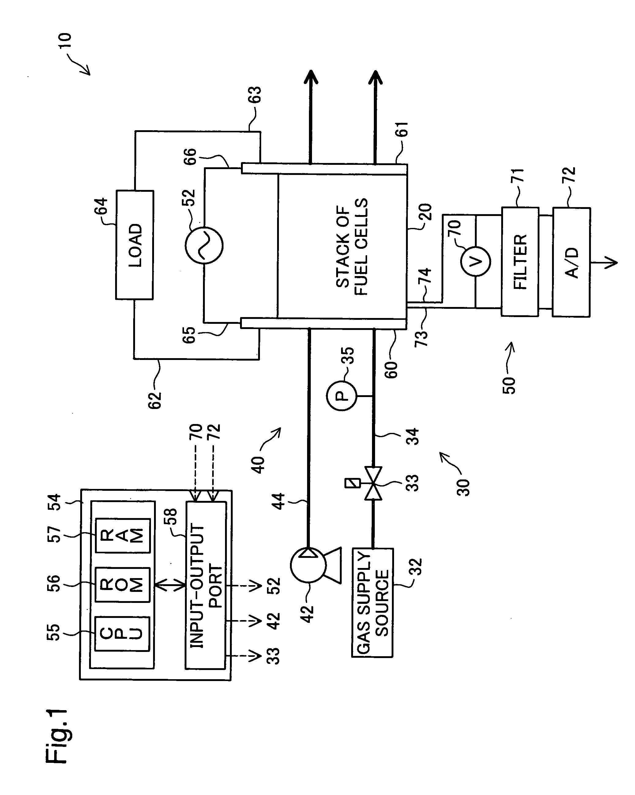
[0018]FIG. 1 is a block diagram schematically illustrating the configuration of a fuel cell system 10 according to one embodiment of the invention. The fuel cell system 10 includes fuel cells 20, a fuel gas supplier 30, and an oxidizing gas supplier 40. The fuel cell system 10 also has a voltage detection assembly 50, an alternating current generator 52, and a controller 54 to monitor the moisture state of the fuel cells 20.

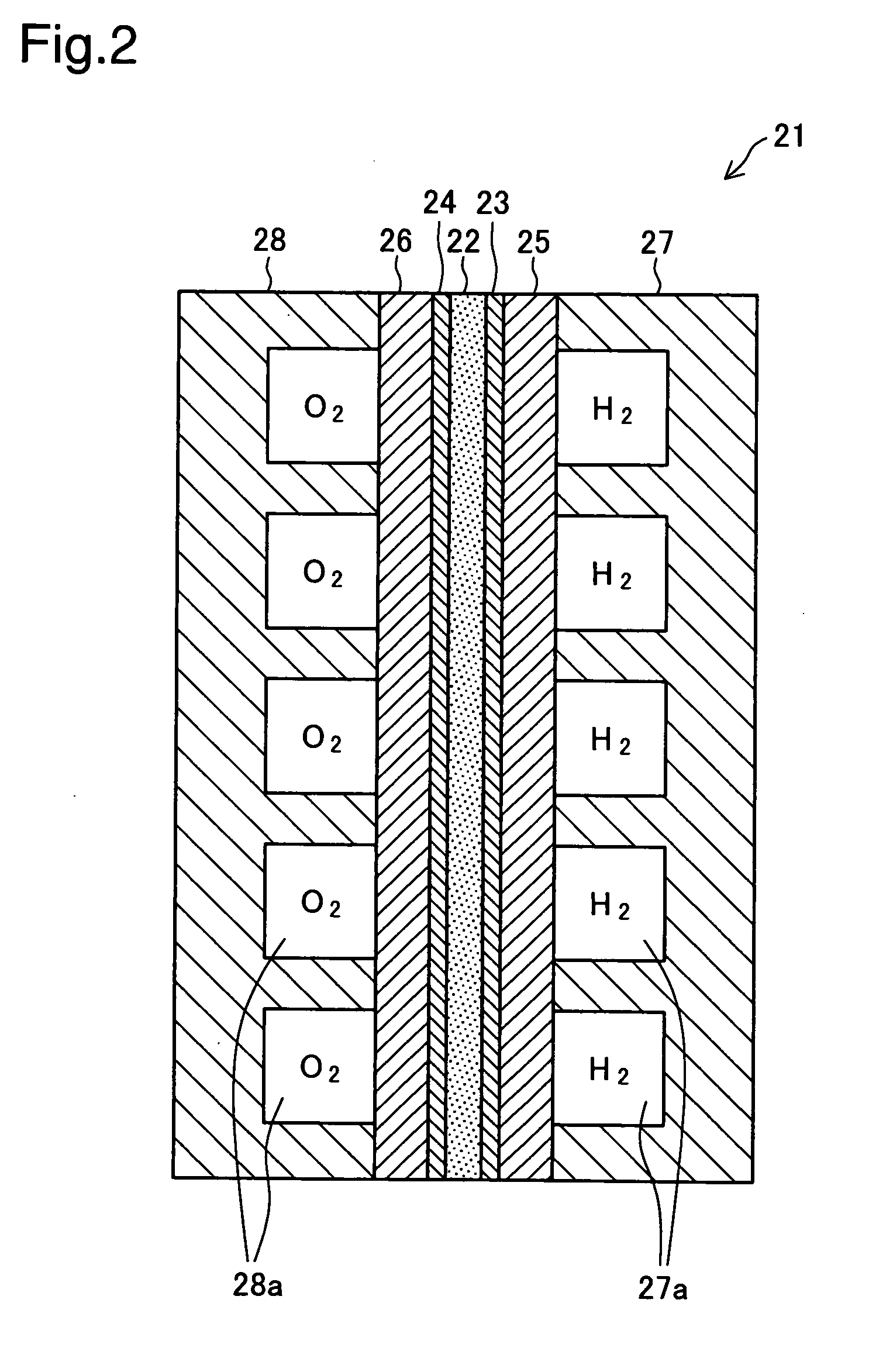
[0019]The fuel cells 20 are polymer electrolyte fuel cells. FIG. 2 is a sectional view schematically showing the structure of a unit cell 21 as a constituent unit of the fuel cells 20. The unit cell 21 includes an electrolyte membrane 22, an anode 23, a cathode 24, a pair of gas diffusion layers 25 and 26, and a pair of separators 27 and 28.

[0020]The electrolyte membrane 22 is a proton-conductive ion exchange membrane ...


PUM


Abstract

In a fuel cell system equipped with polymer electrolyte fuel cells, an alternating current generator applies an alternating current of a fixed frequency and a fixed amplitude to the fuel cells. An alternating current voltage acquisition module (combination of a filter unit and an A-D converter with a controller) extracts an alternating current component attributed to the application of the alternating current from an output voltage in a specific unit cell of the fuel cells and time-sequentially obtains a voltage value of the extracted alternating current component. A moisture state monitoring module (the controller) identifies whether the fuel cells have a moistening tendency. In the case of identification of the moistening tendency of the fuel cells by the moisture state monitoring module, an over-hydration detection module (the controller) computes a statistical value representing a magnitude of a variation in time-sequentially obtained voltage value of the alternating current component and determines that the fuel cells are in an over-hydration state when the computed statistical value representing the magnitude of the variation exceeds a preset reference level.

Description

TECHNICAL FIELD[0001]The present invention relates to a fuel cell system including fuel cells and a driving method of such a fuel cell system.BACKGROUND ART[0002]A solid polymer membrane showing the proton conductivity in the wet state is generally applied to electrolyte layers included in polymer electrolyte fuel cells. It is thus essential to keep the solid polymer membrane in the sufficiently wet state for smooth power generation. Water is produced on cathodes of the fuel cells in the course of power generation. Excessive water production or interrupted discharge of produced water may cause flooding and lead to an insufficient supply of a gas to a cathode catalyst. Control is conventionally performed to keep the water content contained in the electrolyte layer, the catalyst, and their periphery at an adequate level. One known method of controlling the water content determines a moisture state of the electrolyte layer based on a variation in output voltage of each unit cell as a c...

Claims


Application Information

Patent Timeline
IPC IPC(8): H01M8/04H01M8/10
CPCH01M8/04126H01M8/04291H01M8/04365H01M8/04388H01M8/04552Y02E60/50H01M8/04679H01M8/04753H01M8/0485H01M2008/1095H01M8/04641H01M8/04H01M8/10
Inventor ARAKI, YASUSHI
Owner TOYOTA JIDOSHA KK
Why Eureka
Try Eureka