Shower plate, and plasma processing apparatus, plasma processing method and electronic device manufacturing method using the shower plate

a technology of plasma processing apparatus and shower plate, which is applied in the direction of coating, chemical/physical/physical-chemical process, energy-based chemical/physical/physical-chemical process, etc., can solve the problems of high throughput, difficult to perform a uniform process over the entire surface of a target substrate with a high processing rate, and serious drawbacks, so as to improve plasma processing quality and yield, prevent damage on the shower plate, improve the effect of plasma stability

Inactive Publication Date: 2009-11-19
TOKYO ELECTRON LTD +1
View PDF5 Cites 295 Cited by
  • Summary
  • Abstract
  • Description
  • Claims
  • Application Information

AI Technical Summary

Benefits of technology

[0025]In accordance with the present invention, there is no need for installing a cover plate separately as in the conventional shower plate, so that the detachment process or the suspension and lift up process during a cleaning work becomes easy, thereby facilitating the maintenance work and improving the stability of the plasma.
[0026]Further, the generation of abnormal discharge inside the shower plate can be suppressed, so that damage on the shower plate is prevented, thereby enhancing plasma processing quality and yield.

Problems solved by technology

In the conventional plasma processing apparatus, however, since the plasma generation has been non-uniform and the electron density has been found to be high only in a limited region, it has been difficult to perform a uniform process over the entire surface of a target substrate with a high processing rate, i.e., with a high throughput.
Especially, such problem becomes a serious drawback when processing a substrate having a large diameter.
Besides, the conventional plasma processing apparatus also has other crucial problems such as the high electron temperature, the occurrence of damage on a semiconductor device formed on the target substrate, the occurrence of a high level metal contamination due to sputtering a processing chamber wall, and so forth.
Furthermore, as for the conventional plasma processing apparatus, it is getting more and more difficult to meet recent demands for further miniaturization of semiconductor devices or liquid crystal displays and enhancement of productivity.
However, the shower plate having the above-described configuration has problems as follows.
First, there arises a maintenance issue of the shower plate and a stability problem of the plasma.
However, the suspension and lift up process thereof or the installation of the jig has been troublesome.
Further, if the jig is previously installed in the processing chamber for the integration of the shower plate main body and the cover plate, the stability of the plasma is deteriorated due to the presence of the jig.
Moreover, even in case that it is attempted to suspend and lift up the shower plate main body and the cover plate together by using a special suspension jig without their integration beforehand, a cutoff formation process or the like needs to be performed on the shower plate main body and the cover plate to hold the suspension jig, which is troublesome.
Furthermore, the formation of the cutoff or the like may incur damage or deterioration of the plasma stability.
Besides, the suspension and lift up process is also difficult, and deformation of the shower plate is highly likely to occur during the suspension and lift up process.
The deformation of the shower plate would result in deterioration of the plasma stability.
Furthermore, as for the conventional shower plate, since it is necessary to perform position alignment on the shower plate main body and the cover plate, the maintenance work needs to include the position alignment, which is troublesome, too.
If the position alignment is not sufficient, the stability of the generated plasma would be deteriorated.
However, since the microwave electric field is strong inside the shower plate, the O-ring itself is likely to burn when abnormal discharge occurs at a portion of the sealing O-ring or when the shower head is overheated.
In case that the O-ring is burnt, its sealing effect is deteriorated, of course.
Further, the abnormal discharge inside the shower plate may result in damage of the shower plate.Patent Document 1: Japanese Patent Laid-open Publication No.

Method used


Image

  • Shower plate, and plasma processing apparatus, plasma processing method and electronic device manufacturing method using the shower plate
  • Shower plate, and plasma processing apparatus, plasma processing method and electronic device manufacturing method using the shower plate
  • Shower plate, and plasma processing apparatus, plasma processing method and electronic device manufacturing method using the shower plate

Examples


embodiments

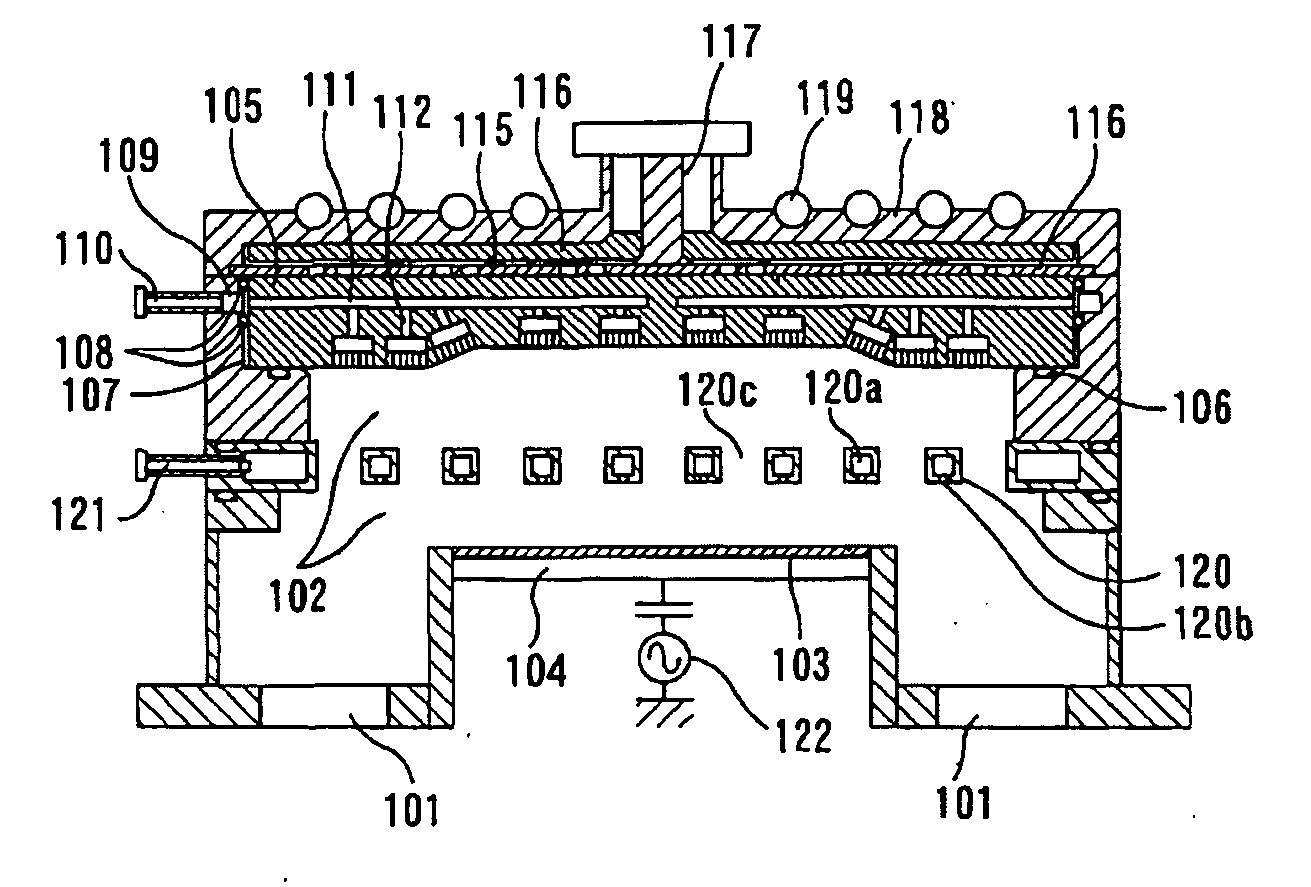
[0028]FIG. 1 illustrates a microwave plasma processing apparatus to which the present invention is applied. The illustrated microwave plasma processing apparatus includes a processing chamber 102 evacuated through a plurality of gas exhaust ports 101, and a supporting table 104 for supporting a target substrate 103 is disposed in the processing chamber 102. The processing chamber 102 defines a ring-shaped space around the supporting table 104 in order to evacuate the processing chamber 102 uniformly, and the plurality of gas exhaust ports 101 is arranged at a same interval, i.e., in axial symmetry with respect to the target substrate 103, while communicating with the space. With such arrangement of the gas exhaust ports 101, the processing chamber 102 can be evacuated through the gas exhaust ports 101 uniformly.

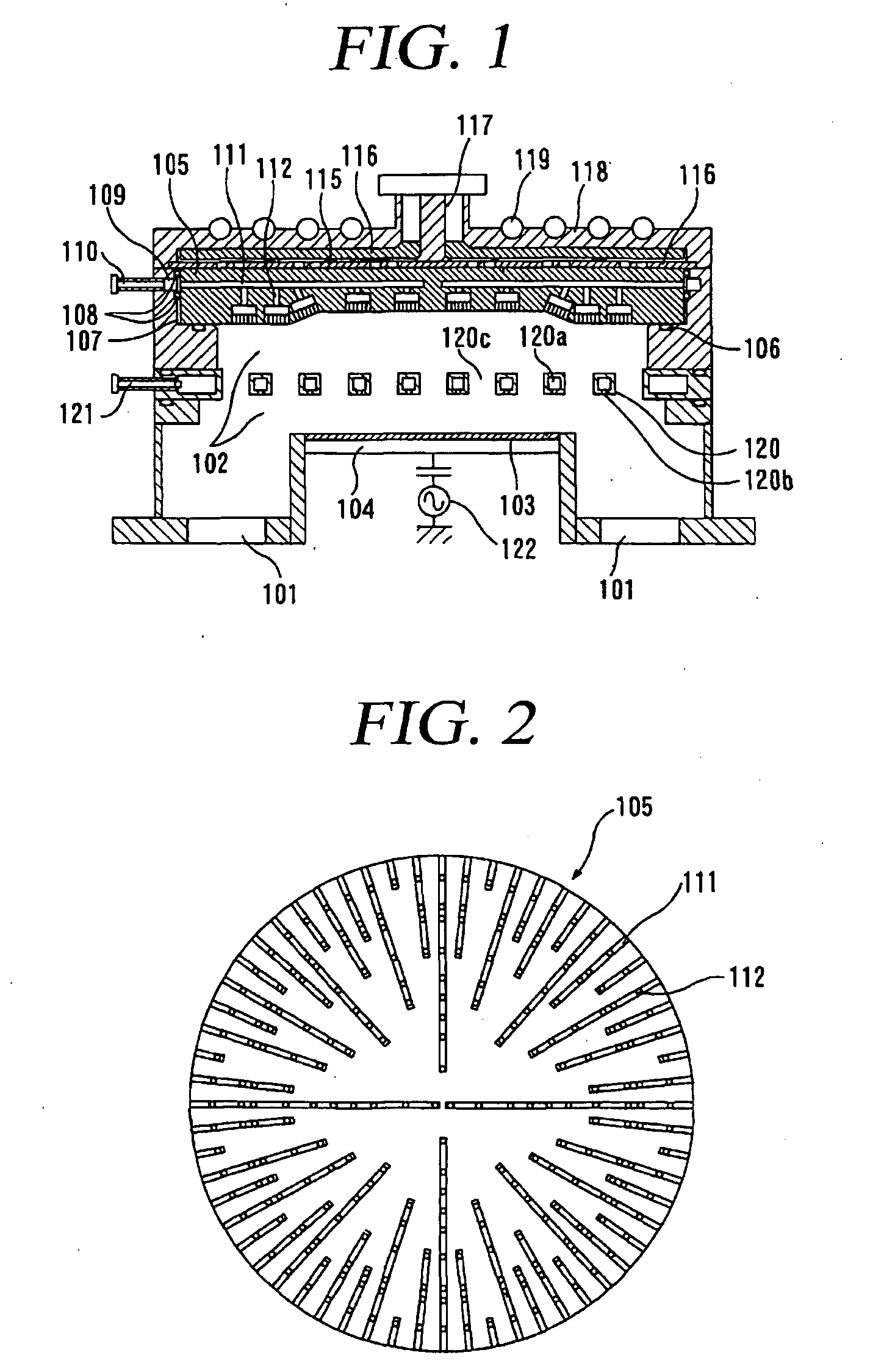
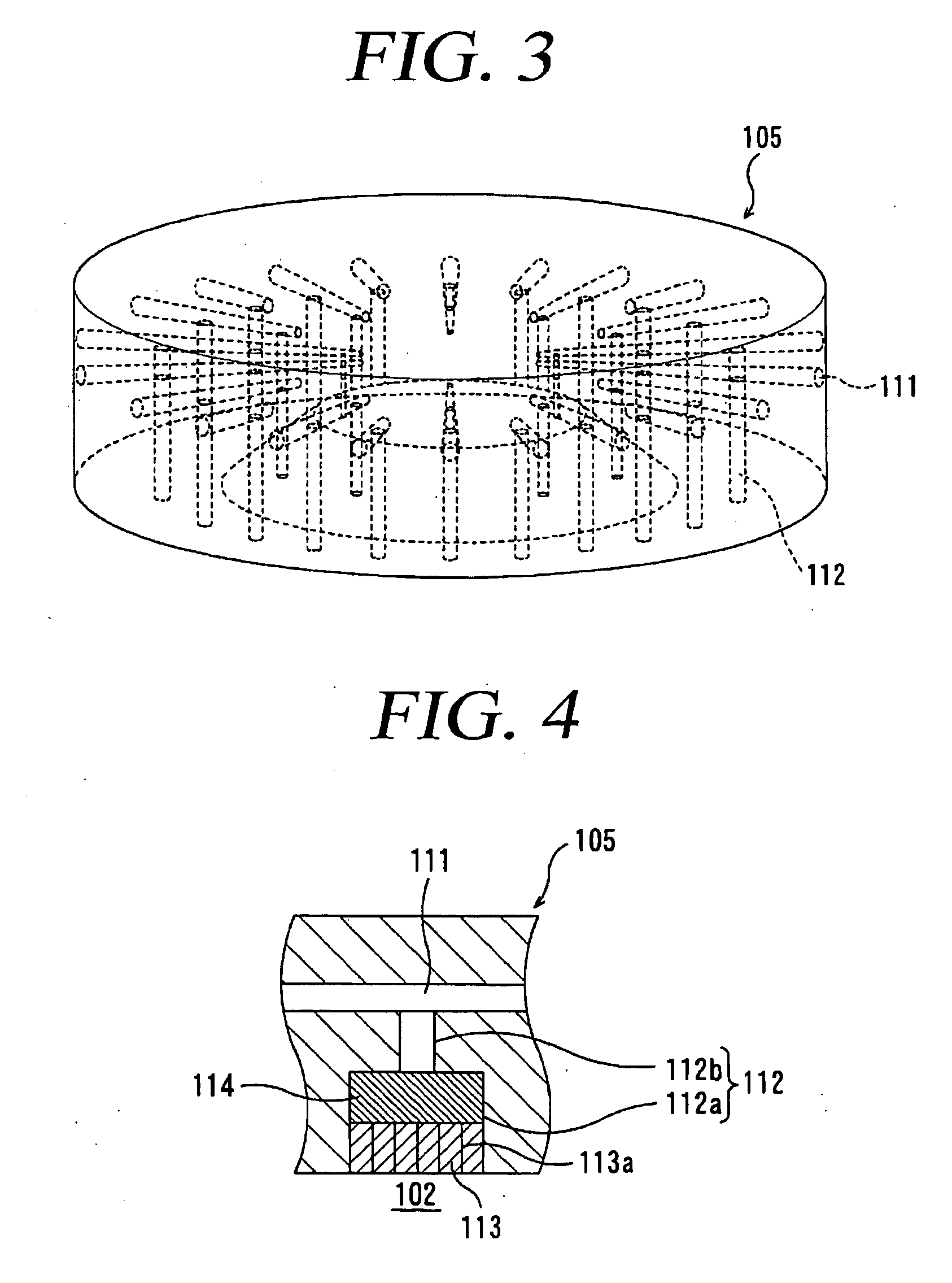
[0029]Disposed at an upper portion of the processing chamber 102 via a sealing O-ring 106 is a shower plate 105 which has a diameter of about 408 mm and a dielectric constant...


PUM

PropertyMeasurementUnit
gate lengthaaaaaaaaaa
diameteraaaaaaaaaa
dielectric constantaaaaaaaaaa

Abstract

Provided is a shower plate in which there's no need for a cover plate. The shower plate 105 is disposed in a processing chamber 102 of a plasma processing apparatus, for discharging a plasma excitation gas to generate plasma in the processing chamber 102, and the shower plate 105 includes a horizontal hole 111 for introducing the plasma excitation gas into the shower plate 105 from a gas inlet port 110 of the plasma processing apparatus; and a vertical hole 112 communicating with the horizontal hole 111, wherein the shower plate 105 is formed as a single body.

Description

TECHNICAL FIELD[0001]The present invention relates to a shower plate used in a plasma processing apparatus, more particularly, a microwave plasma processing apparatus, and a plasma processing apparatus, a plasma processing method and an electronic device manufacturing method using the shower plate.BACKGROUND ART[0002]A plasma process and a plasma processing apparatus are essential for the manufacture of a recent ultrafine semiconductor device called a deep sub-micron device or deep sub-quarter micron device having a gate length of about 0.1 μm or less, or the manufacture of a flat panel display of a high-resolution including a liquid crystal display.[0003]Various plasma excitation methods are conventionally adopted for the plasma processing apparatus for use in the manufacture of the semiconductor device or the liquid crystal display. Especially, a high-frequency excitation plasma processing apparatus of a parallel plate type or an inductively coupled plasma processing apparatus is ...

Claims


Application Information

Patent Timeline
Patent Type & Authority Applications(United States)
IPC IPC(8): H01L21/3065C23C16/00H01L21/30B01J19/08
CPCC23C16/455C23C16/45565H01J37/32449C23C16/511H01J37/3244C23C16/45572H01L21/3065
Inventor OKESAKU, MASAHIROGOTO, TETSUYAOHMI, TADAHIROISHIBASHI, KIYOTAKA
Owner TOKYO ELECTRON LTD
Why Eureka
Try Eureka