
Burner And Method For The Regeneration Of Filtration Cartridges And Devices Equipped With Such Burner

Inactive Publication Date: 2009-11-26
FAYARD JEAN CLAUDE
View PDF14 Cites 26 Cited by
  • Summary
  • Abstract
  • Description
  • Claims
  • Application Information

AI Technical Summary

Benefits of technology

[0043]According to the invention, the burner further comprises: at least one intake duct for a mixture of fuel and oxidiser terminating in the burner body in a direction essentially tangential to the burner body, so as to apply a swirl motion to the said mixture inside the burner body; electrical ignition means for igniting the said mixture, positioned inside the burner body; a closure element obstructing a substantial portion of the burner body, so as to limit the turbulence that may be generated by the said exhaust gases on the fluid flows within the volume of the burner body bounded by the said closure element.
[0080]In other words, the method according to the present invention serves to ignite the mixture in the burner regardless of the exhaust gas flows, because means limit their turbulence therein to a level compatible with the ignition of the mixture, injected in a manner suitable for ignition. This serves to easily ignite the mixture in a zone protected from turbulence, bounded by the closure element.

Problems solved by technology

However, they have no effect on the emissions of solid particulates.
Thus, such catalysts provide no significant improvement in the emissions of diesel engines producing numerous solid particulates.
In fact, modifying the combustion of the engines is no longer sufficient to comply with the directives on releases.
In addition to decreasing the engine performance due to the pressure drops caused by the clogging of the particulate filter, engines equipped with a particulate filter of the prior art are liable to undergo another detrimental process.
This is because, since the clogging misadjusts the engine, the exhaust temperature is liable to rise, thereby causing the sudden and unintended combustion of a large mass of solid particulates, so that the temperature rises to levels much higher than 1000° C., possibly exceeding the thermal resistance of the abovementioned materials constituting the filter cartridge.
The thermal shock resulting from such a combustion may therefore have a detrimental impact on the structure of the particulate filter.
However, the major difficulty for ensuring the operation of such particulate filters resides in the possibility of implementing the phases of oxidation and combustion of the solid particulates retained by the filter cartridge.
In fact, in the absence of chemical additives, the carbonaceous particles produced by the combustion of diesel fuel in a diesel engine only begin to oxidise above a temperature of 450° C. and to be consumed from 550° C. However, such temperatures are practically never reached in practice in city driving conditions.
Such fuels are only available in a few countries that impose such a limit on their sulphur content, a limit that is nonexistent in many emerging countries.
Moreover, to ensure satisfactory operation of the filters, this technique requires a regular regeneration in order to limit the pressure drop of the filter while eliminating the risk of uncontrolled regeneration, which is therefore too exothermic and destructive for the filter cartridge.
In the opposite case, due to the excessive concentration of carbonaceous particulates clogging the filter, the abovementioned violent reactions occur, consisting of an excessively rapid combustion of a large mass of solid particulates, which generally leads to destruction of the filter by thermal shock, since the temperatures obtained may be very high locally.
A first drawback of such a solution resides in the very high cost of the additives to be used.
Moreover, it is necessary to provide a device for introducing the supplementary additive, which further increases the cost of such a solution.
Furthermore, the additives present in the carbonaceous materials contribute to the even faster fouling of the filter cartridge.
In consequence, a solution of this type increases the risk of clogging of the particulate filter and hence of uncontrolled reactions, when the temperatures reached in operation are not sufficiently high.
However, such methods have the common drawback, on the one hand, of not allowing optimal, safe and economical regeneration of the filtration means, and, on the other, of undergoing thermal degradation and coking of the regeneration liquid, particularly when the fuel is diesel, especially in the post-injection injector nozzles.
The post-injection means are thereby rapidly damaged by the heat generated by the exhaust manifold, thereby reducing their reliability and efficiency.
Furthermore, the known post-injection methods only operate satisfactorily if a minimum exhaust gas temperature of about 300° C. is reached during at least 5% of the operating time.
In consequence, the devices and methods implementing diesel post-injection in the exhaust gases upstream of an oxidation catalyst become inadequate when the temperature is too low.
Another drawback of these systems resides in the spurious and pollutant hydrocarbon emissions generated during the injection phase, when the temperatures are too low, for example around 300° C.
In fact, this implies numerous drawbacks, among which mention can be made of the difficulty of controlling, or even simply initiating, the combustion in the burner, the difficulty of thermally insulating the filter, the high temperature rise of the burner during the combustion phase (above 1400° C.) and the necessity to have a high filtration capacity to ensure sufficiently long service, that is between two engine stops.
In most cases, the use of a burner to provide the heat necessary for combustion of the solid particulates is only satisfactory when the engine is stopped or idling, that is at the time when the regeneration conditions are the least favourable, because the exhaust gas temperature is then low.
Moreover, due to the burning powers required, most of the devices have a size that is incompatible with the volume generally available in the particulate filter.
Furthermore, such burners encounter serious difficulties in operating satisfactorily during the normal running of the engine, due to the difficulty of igniting the burner due to the high turbulence prevailing in the exhaust line and hence in the burner.
Such burners consequently demand bulky and sophisticated systems, which are therefore expensive, to overcome these problems.

Method used


Image

  • Burner And Method For The Regeneration Of Filtration Cartridges And Devices Equipped With Such Burner
  • Burner And Method For The Regeneration Of Filtration Cartridges And Devices Equipped With Such Burner
  • Burner And Method For The Regeneration Of Filtration Cartridges And Devices Equipped With Such Burner

Examples


Embodiment Construction

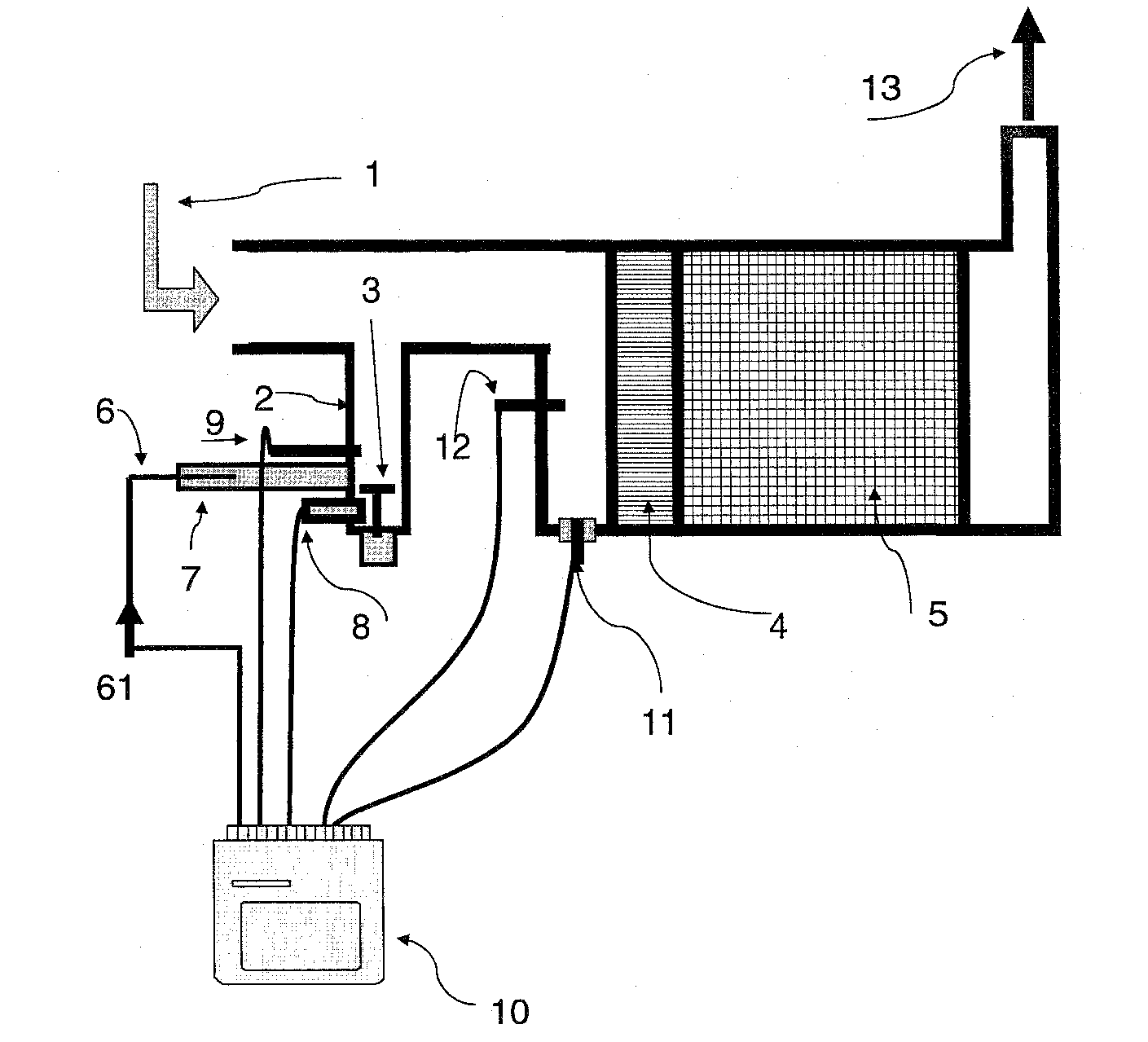
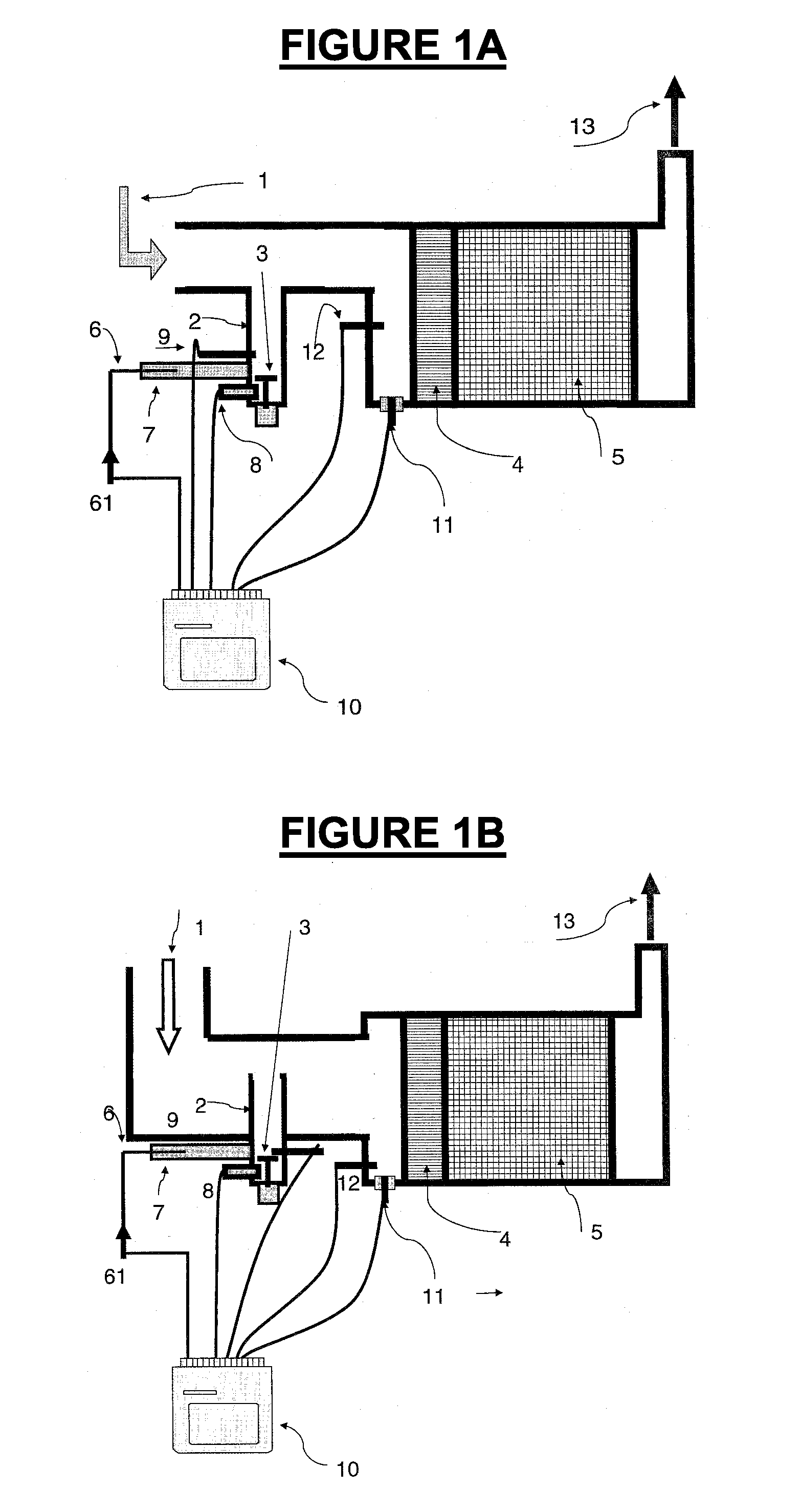
[0102]In the exhaust lines shown in FIGS. 1A and 1B, the exhaust gases from the diesel engine reach the filtration device via an inlet 1, at a temperature which may be between 80° C. at idling and 400° C. under load. Such exhaust lines are each equipped with a catalyst 4, followed by a filter cartridge 5, upstream of which a burner according to the invention is mounted.

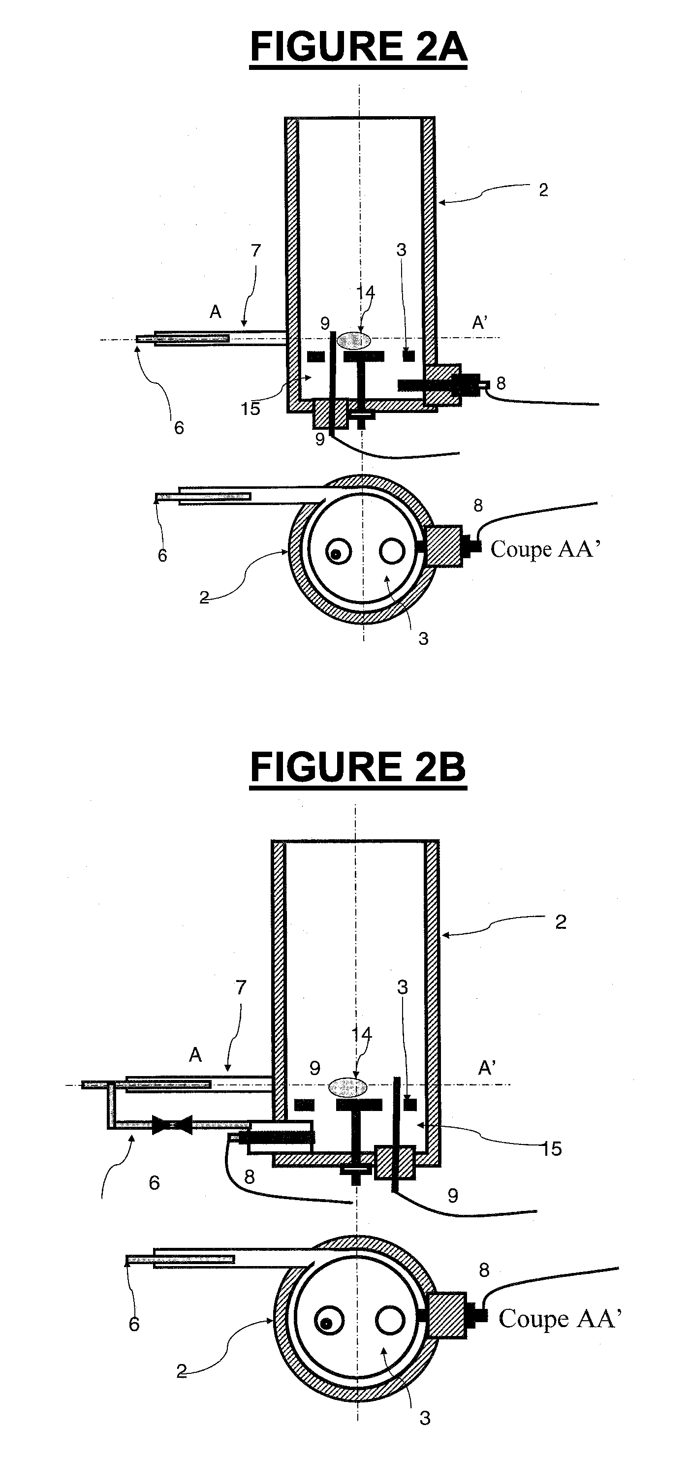
[0103]In the present case, the burner has a burner body 2 with a symmetry of revolution comprising, according to one feature of the invention, a closure element 3 positioned within the burner body 2.

[0104]An intake duct 7 for a mixture of fuel and oxidiser discharges tangentially into the burner body 2, in order to convey the diesel or other fuel therein, led into the duct 7 via a capillary 6, itself fed by an injector 61. Means (not shown) are in fact provided for communicating an appropriate momentum to the oxidiser and to the fuel for applying a swirl movement to the mixture in the burner body 2. Typically, the spe...


PUM


Abstract

A burner for heating a filter cartridge for the exhaust gases of an engine until the oxidation and / or combustion of the solid particulates trapped in the cartridge, including a burner body having a closed end and, on the side opposite this closed end, an opening for removing the said gases. The burner further including at least one intake duct for a mixture of fuel and oxidiser terminating in the burner body tangentially to the burner body, so as to cause the mixture to swirl in the burner; an electrical ignition means for igniting the said mixture positioned inside the burner body; and a closure element obstructing the burner body, to limit the turbulence of the exhaust gases in the volume of the burner body bounded by the said closure element.

Description

CROSS REFERENCE TO RELATED APPLICATIONS[0001]This application is a National Stage filing under 35 U.S.C. §371 of PCT Application No. PCT / FR2007 / 050982, filed Mar. 22, 2007. This application also claims the benefit of French Application No. 0652501, filed Jun. 7, 2006. The entirety of both applications is incorporated herein by reference.FIELD OF THE INVENTION[0002]The present invention relates in general to the field of the reduction, or even the complete removal, of the solid particulates such as soot contained in the exhaust gases of an internal combustion engine, and issuing in particular from diesel engines.[0003]More particularly, the invention relates to a method for regenerating the filter cartridge(s) by burning the soot trapped therein. The term “regeneration” means the restoration of the filter cartridge to an operating state similar to its initial state.BACKGROUND OF THE INVENTION[0004]The authorities have established increasingly stringent standards to require automobile...

Claims


Application Information

Patent Timeline
IPC IPC(8): F01N3/023F01N3/10
CPCF01N3/0256Y02T10/47F01N2240/14F01N9/002Y02T10/40
Inventor FAYARD, JEAN-CLAUDE
Owner FAYARD JEAN CLAUDE
Features
  • Generate Ideas
  • Intellectual Property
  • Life Sciences
  • Materials
  • Tech Scout
  • Unparalleled Data Quality
  • Higher Quality Content
  • 60% Fewer Hallucinations
Learn More