Fluorescent image obtainment method and apparatus, fluorescence endoscope, and excitation-light unit

a fluorescence endoscope and fluorescent image technology, applied in the direction of luminescent dosimeters, optical radiation measurement, diagnostics using spectroscopy, etc., can solve the problems of insufficient, inability to accurately judge the tissue characteristics of the region to be observed, and risk of dark image obtained, so as to achieve the effect of safe handling of the excitation light uni

a fluorescence endoscope and fluorescent image technology, applied in the direction of luminescent dosimeters, optical radiation measurement, diagnostics using spectroscopy, etc., can solve the problems of insufficient, inability to accurately judge the tissue characteristics of the region to be observed, and risk of dark image obtained, so as to achieve the effect of safe handling of the excitation light uni

US20090289200A1Inactive Publication Date: 2009-11-26FUJIFILM CORP

Image

  • Fluorescent image obtainment method and apparatus, fluorescence endoscope, and excitation-light unit
  • Fluorescent image obtainment method and apparatus, fluorescence endoscope, and excitation-light unit
  • Fluorescent image obtainment method and apparatus, fluorescence endoscope, and excitation-light unit

Examples


first embodiment

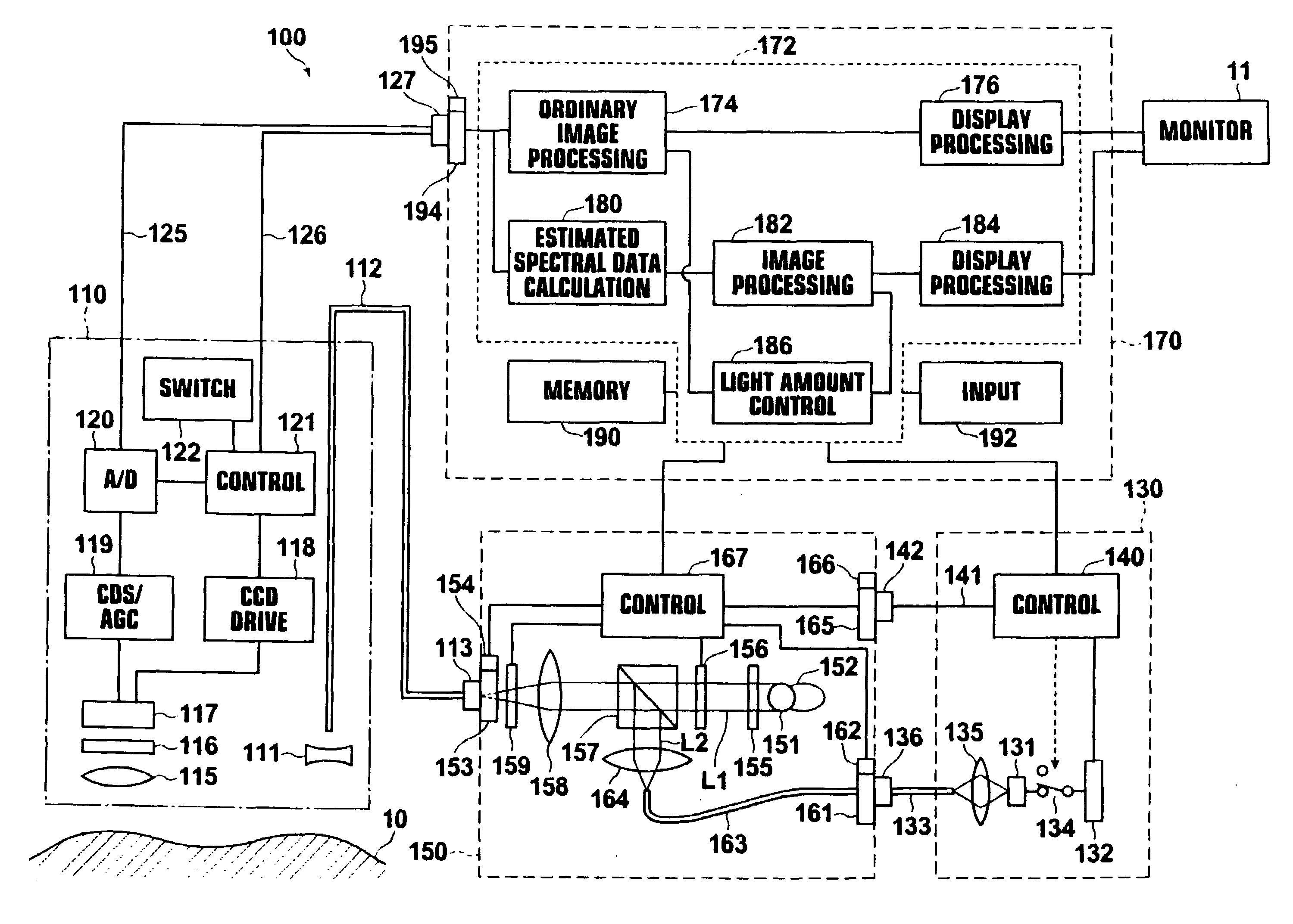
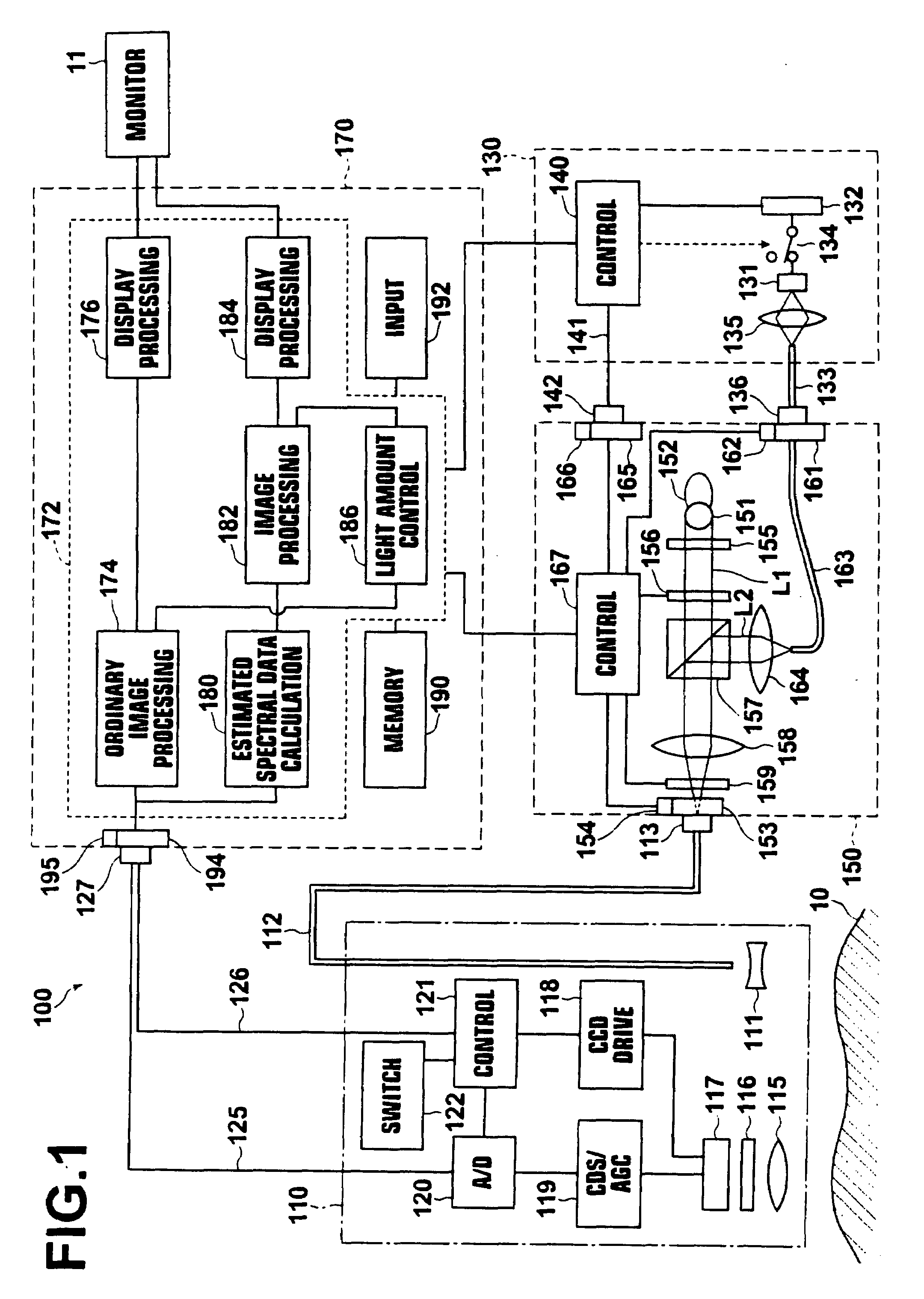
[0212]The scope unit 110 and the illumination light unit 150 are structured in a manner similar to those of the fluorescence endoscope apparatus of the

[0213]The excitation light unit 230 includes a GaN-based semiconductor laser 231 that outputs the excitation light L2, a drive circuit 232 that drives the semiconductor laser 231, and a light guide 233 that guides the excitation light L2 output from the semiconductor laser 231. The light guide 233 extends from the case of the excitation light unit 230, and the other end of the light guide 233 is connected to the optical connector 236. The optical connector 236 is detachably connected to the optical connector 161 of the illumination light unit 150. A switch 234 is provided between the semiconductor laser 231 and the drive circuit 232, and a light-condensing optical system 235 is provided between the semiconductor laser 231 and an end (light incident end) of the light guide 233.

[0214]In the fluorescence endoscope apparatus 200 of the pr...

second embodiment

[0300]Further, as illustrated in FIG. 14, a spectral image processing unit 388 may be provided in the fluorescence endoscope apparatus of the above embodiments. The spectral image processing unit 388 may perform spectral image processing on at least one of the ordinary image signal composed of RGB image signals, obtained in the ordinary image processing unit 374, the combined image signal composed of RGB image signals, obtained in the fluorescent image processing unit 382, and the fluorescent image signal obtained in the fluorescent image processing unit 382. Further, whether the spectral image processing is performed may be selected by an input operation at the input unit 392. The action in the case of performing spectral image processing on the ordinary image signal, the fluorescent image signal or the combined image signal is similar to the action of the fluorescence endoscope apparatus of the

[0301]Further, the spectral image processing unit 388 may obtain a fluorescence yield, a...


PUM


Abstract

A fluorescent image obtainment apparatus includes a light illumination means that illuminates a region to be observed with illumination-light and excitation-light at the same time, and an imaging means that captures an image composed of light reflected from the region illuminated with the illumination-light and an image composed of fluorescence output from the region illuminated with the excitation-light. Further, the apparatus includes an image processing means that produces an ordinary image based on the image of the reflection light and a fluorescent image based on the image of fluorescence, and a light amount control means that controls the light amount of the illumination-light so that a representative luminance value of the ordinary image becomes a predetermined luminance value and the light amount of the excitation-light so that the ratio of the light amount of the excitation-light to that of the illumination-light becomes a predetermined ratio.

Description

BACKGROUND OF THE INVENTION[0001]1. Field of the Invention[0002]The present invention relates to a fluorescent image obtainment method, a fluorescent image obtainment apparatus, a fluorescence endoscope apparatus, and an excitation light unit. Particularly, the present invention relates to a fluorescent image obtainment method, a fluorescent image obtainment apparatus and a fluorescence endoscope apparatus that produce a fluorescent image by obtaining an image including fluorescence output from a region to be observed by illumination with excitation light. Further, the present invention relates to an excitation light unit that outputs excitation light to produce the fluorescent image.[0003]2. Description of the Related Art[0004]Conventionally, endoscope apparatuses for observing tissue in the body cavities of patients (in vivo) have been widely known. Further, electronic endoscopes that obtain ordinary images by imaging regions to be observed in the body cavities while the regions a...

Claims


Application Information

Patent Timeline
26 Nov 2009
Publication
US20090289200A1
IPC
G01N21/64
CPC
A61B1/00009; A61B1/042; A61B1/043; A61B1/0638; A61B1/0669; A61B5/0075; A61B5/0084; A61B1/063
Inventors
ISHII, SHUICHI