
Adaptive echo cancellation for an on-frequency RF repeater with digital sub-band filtering

a technology of echo cancellation and on-frequency rf repeater, applied in the field of echo cancellation systems and methods for on-frequency rf repeaters, can solve problems such as the failure of correlation-based methods such as in the above published '699 application'

Active Publication Date: 2009-11-26
INTEL CORP
View PDF2 Cites 33 Cited by
  • Summary
  • Abstract
  • Description
  • Claims
  • Application Information

AI Technical Summary

Benefits of technology

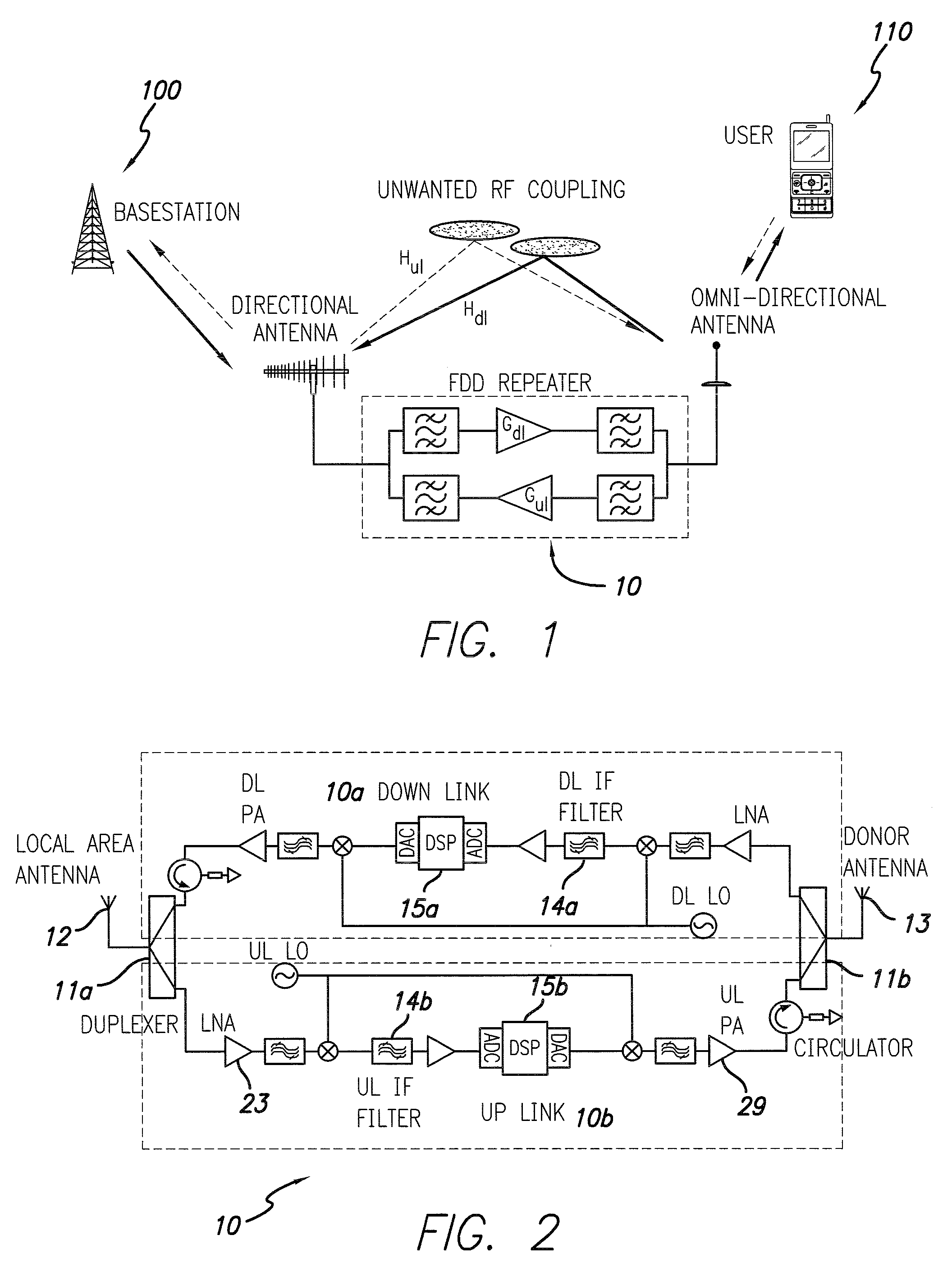
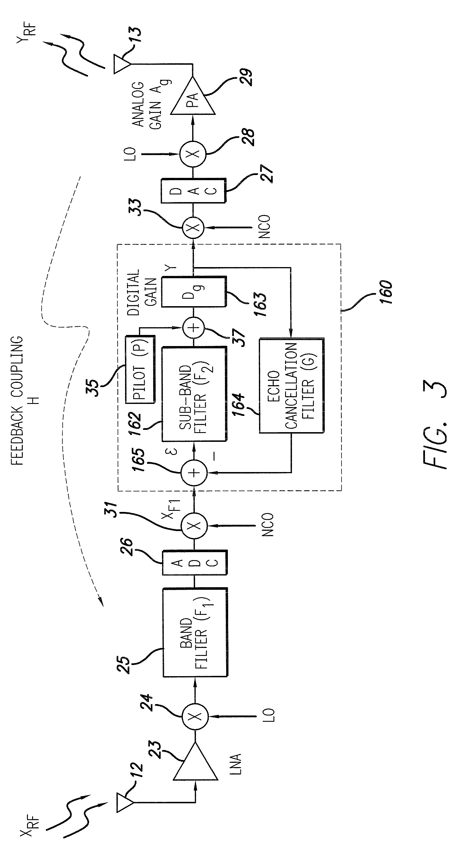
The present invention provides a wireless repeater with an improved echo cancellation function. The repeater has an input antenna for receiving an input signal, an output antenna for outputting an amplified signal, an amplifier for amplifying the received input signal, a band filter for limiting the input signal to an operational frequency band of the repeater, and a sub-band filter for limiting the output of the band filter to one or more sub-bands within the operational frequency band. The repeater also has a digital feedback path coupled to the output of the sub-band filter and including a digital signal processor for adaptively canceling an echo between the output antenna and the input antenna by implementing an adaptive algorithm based on cross and autocorrelation measurements obtained from the power spectrum of a signal representing the digital output of the repeater. The repeater may also have a pilot signal source coupled to insert a broad spectrum pilot signal to the output of the sub-band filter to assist in the calculation of the cross and power spectrums. The method can be implemented in an on frequency repeater where the input signal includes a narrowband signal. The technical effect of the invention is to improve the echo cancellation function of the wireless repeater.

Problems solved by technology

However, correlation-based methods such as in the above published '699 application can fail when the input signal comprises a strong narrowband component, such as GSM, because the auto-correlation of the input signal and echo overlap.

Method used


Image

  • Adaptive echo cancellation for an on-frequency RF repeater with digital sub-band filtering
  • Adaptive echo cancellation for an on-frequency RF repeater with digital sub-band filtering
  • Adaptive echo cancellation for an on-frequency RF repeater with digital sub-band filtering

Examples


Embodiment Construction

[0024]The present disclosure may incorporate the teachings set out in R. N. Braithwaite and S. Carichner, “Adaptive Echo Cancellation for an On-Frequency RF Repeater using a Weighted Power Spectrum”, U.S. patent application Ser. No. 12 / 009,667 filed Jan. 22, 2008, the disclosure of which is incorporated herein by reference in its entirety.

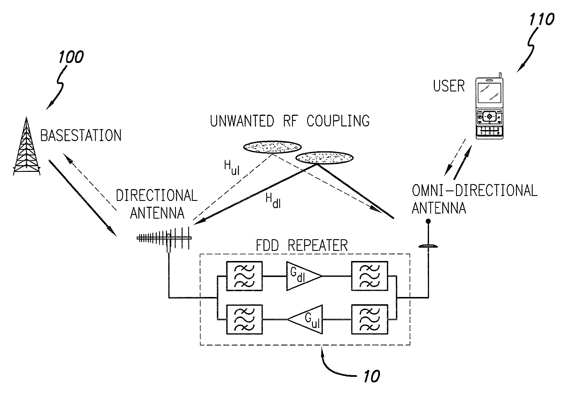
[0025]The present invention provides an improved wireless communication system employing a bi-directional on-frequency repeater in accordance with the invention. An on-frequency RF repeater extends the coverage of a basestation by receiving, filtering, and re-transmitting signals of interest at the same frequency and at a higher power level. Typically the repeater is bi-directional providing gain to both the up link and down link connecting the basestation and mobile user, as depicted in FIG. 1. Unwanted RF coupling between the input and output antennas of a high gain repeater causes delayed and attenuated replicas of the original signal, referred ...


PUM


Abstract

An adaptive echo cancellation system and method employing an algorithm suitable for a digital repeater with sub-band filtering is disclosed. Cross- and auto-correlation measurements used to estimate the residual coupling are computed from normalized cross and power spectrums which avoid the problems associated with narrow bandwidth signal components. The normalized cross- and power spectra are additionally masked in frequency to reduce the influence of interfering spectral components outside of the passband of the sub-band filter. Regularization of the iterative estimation process is applied to maintain stability and compensate for the bandwidth reduction associated with the sub-band filter and the spectral mask.

Description

RELATED APPLICATION INFORMATION[0001]The present application claims the benefit under 35 USC 119(e) of provisional application Ser. No. 61 / 128,366 filed May 20, 2008.BACKGROUND OF THE INVENTION[0002]1. Field of the Invention[0003]The present invention relates to radio frequency (RF) repeaters. More particularly, the present invention relates to echo cancellation systems and methods for an on-frequency RF repeater.[0004]2. Description of the Prior Art and Related Information[0005]An on-frequency RF repeater extends the coverage of a basestation by receiving, filtering, and re-transmitting signals of interest at the same frequency and at a higher power level. Repeaters with high forward gain often exhibit echoes due to RF coupling between the input and output antennas. Echo cancellation is employed to reduce the echo. One approach to echo cancellation which employs autocorrelation techniques is disclosed in T. Pham and M. P. Fuerter, “System for convolutional echo cancellation by iter...

Claims


Application Information

Patent Timeline
Patent Type & Authority Applications(United States)
IPC IPC(8): H04B3/36
CPCH04B7/15585
Inventor BRAITHWAITE, RICHARD NEILCARICHNER, SCOTTCOPE, MARK
Owner INTEL CORP
Learn More