Hard Component Failure Detection and Correction

Active Publication Date: 2009-11-26
ORACLE INT CORP
View PDF19 Cites 25 Cited by
  • Summary
  • Abstract
  • Description
  • Claims
  • Application Information

AI Technical Summary

Benefits of technology

[0009]In one embodiment, a memory controller comprises a check bit encoder circuit coupled to receive a data block to be written to memory, a check/correct circuit coupled to receive an encoded data block read from the memory, and a hard failure detection circuit coupled to the check/correct circuit. The check bit encoder circuit is configured to generate a corresponding encoded data block comprising the data block, a first plurality of check bits, and a second plurality of check bits. The check/correct circuit is configured to detect an error in the encoded data block responsive to the first plurality of check bits, the second plurality of check bits, and the data block within the encoded data block. The en

Problems solved by technology

Component failures are a common source of error in electrical systems.
Faulty components may include faulty memory chips or faulty data paths provided between devices of a system.
Faulty data paths can result from, for example, faulty pins, faulty data traces, or faulty wires.
Additionally, memory modules, which may contain multiple memory chips, may fail.
Circuitry which drives the data paths may also fail.
Another source of error in electrical systems may be so-called “so

Method used


Image

  • Hard Component Failure Detection and Correction
  • Hard Component Failure Detection and Correction
  • Hard Component Failure Detection and Correction

Examples


Embodiment Construction

Apparatus Overview

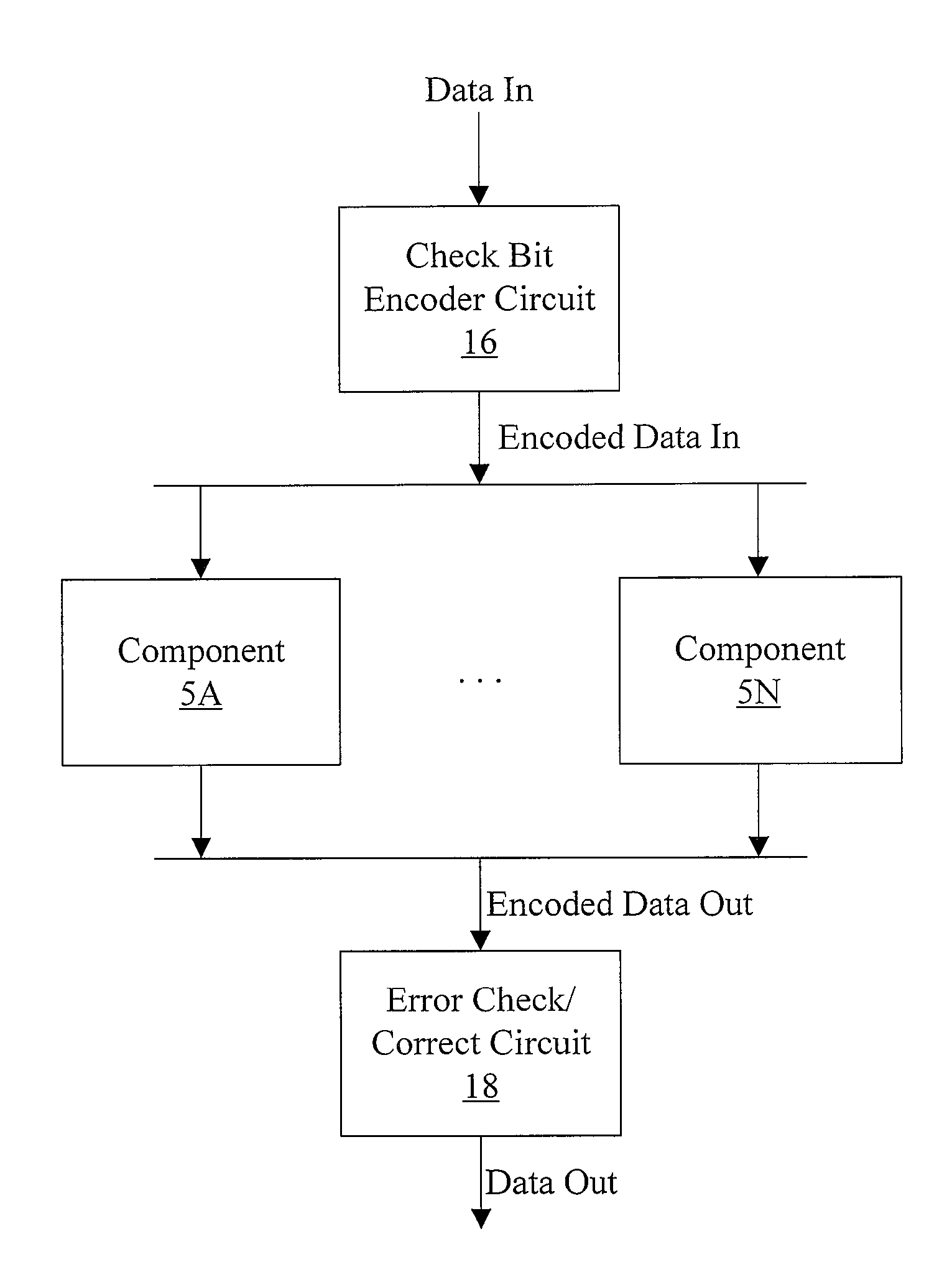
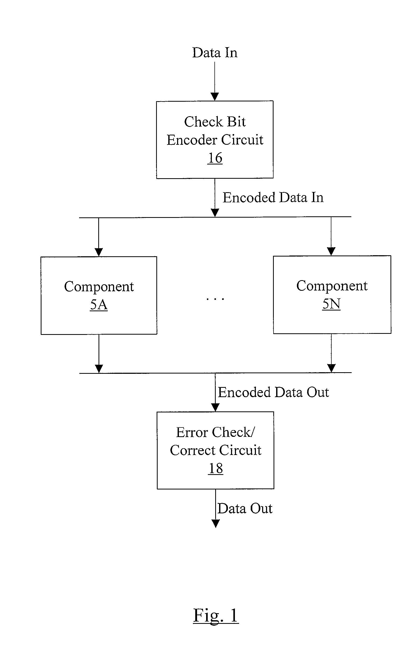
[0025]Turning now to FIG. 1, a block diagram of one embodiment of an apparatus including a check bit encoder circuit 16, a plurality of components 5A-5N, and an error check / correct circuit 18 is shown. In the embodiment of FIG. 1, the check bit encoder circuit 16 is coupled to receive input data (Data In in FIG. 1) and to provide corresponding encoded data (Encoded Data In in FIG. 1) to the components 5A-5N. The components 5A-5N are coupled to receive the encoded data from the check bit encoder circuit 16 and to provide encoded data (Encoded Data Out in FIG. 1) to the error check / correct circuit 18, which is configured to provide corresponding output data (Data Out in FIG. 1).

[0026]The apparatus may operate on data blocks, and may encode the data blocks with check bits to provide for error detection and correction of the data blocks. More particularly, the check bit encoder circuit 16 may receive a data block and may generate a corresponding encoded data block incl...


PUM


Abstract

In one embodiment, a memory controller comprises a check bit encoder circuit coupled to receive a data block to be written to memory, a check/correct circuit coupled to receive an encoded data block read from the memory, and a hard failure detection circuit coupled to the check/correct circuit. The check bit encoder circuit is configured to generate a corresponding encoded data block comprising the data block, a first plurality of check bits, and a second plurality of check bits. The check/correct circuit is configured to detect an error in the encoded data block responsive to the first check bits, the second check bits, and the data block within the encoded data block, which is logically arranged as an array of R rows and N columns, wherein R and N are positive integers. Each of the first check bits covers a respective row of the array, and the check/correct circuit is configured to generate a first syndrome corresponding to the first plurality of check bits. A presence of more than one binary one in the first syndrome indicates a multi-bit error. Responsive to detecting the multi-bit error, the hard failure detection circuit is configured to perform a plurality of memory read/write operations to the memory locations in which the encoded data block is stored to identify a hard error failure in the memory.

Description

BACKGROUND OF THE INVENTION[0001]1. Field of the Invention[0002]This invention is related to error correction code (ECC) systems.[0003]2. Description of the Related Art[0004]Error codes are commonly used in electronic systems to detect and correct data errors, such as transmission errors or storage errors. For example, error codes may be used to detect and correct errors in data transmitted via any transmission medium (e.g. conductors and / or transmitting devices between chips in an electronic system, a network connect, a telephone line, a radio transmitter, etc.). Error codes may additionally be used to detect and correct errors associated with data stored in the memory of computer systems. One common use of error codes is to detect and correct errors of data transmitted on a data bus of a computer system. In such systems, error correction bits, or check bits, may be generated for the data prior to its transfer or storage. When the data is received or retrieved, the check bits may b...

Claims


Application Information

Patent Timeline
IPC IPC(8): H03M13/00
CPCG06F11/10H04L1/0041H04L1/22H04L2001/0096
Inventor CYPHER, ROBERT E.
Owner ORACLE INT CORP
Why Eureka
Try Eureka