Wire saw slurry recycling process
a technology of slurry and wire saw, which is applied in the direction of gas current separation, other chemical processes, manufacturing tools, etc., can solve the problem of reducing the cutting effectiveness of slurry
- Summary
- Abstract
- Description
- Claims
- Application Information
AI Technical Summary
Problems solved by technology
Method used
Image
Examples
example 1
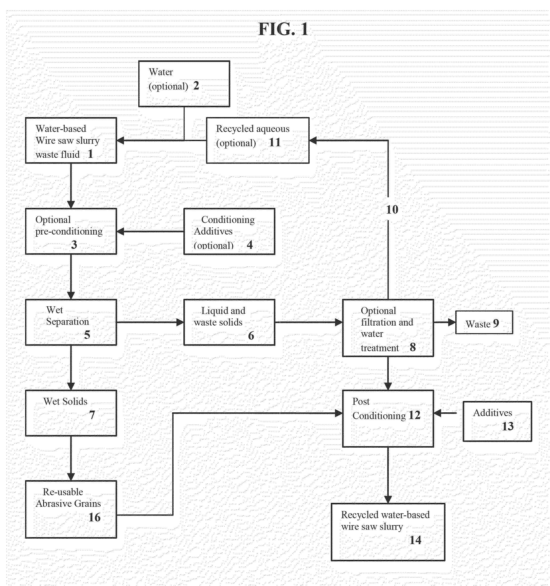
[0034]In contrast, water-based wire saw cutting slurry waste fluid containing about 45 wt % SiC abrasive particles and about 10 wt % Si kerf particles can be processed on the same centrifuge system as described in the comparative example. The aqueous carrier fraction of this waste fluid generally contains greater than 85 wt % water. Prior to processing, the water content of water-based wire saw cutting slurry waste fluid can be adjusted by adding water. For example, the waste fluid may be diluted with sufficient water to bring the water content of the aqueous carrier of the waste fluid to the desired range. When the first stage centrifuge of the two-stage system is operated under the same normal conditions as described in the comparative example, generally more than 85% of the SiC abrasive will be recovered in the centrifuge underflow, with less than 20% of Si kerf remaining in the recovered abrasive. A higher water content in the waste fluid will generally lead to increased abrasiv...
example 2
[0037]A water-based wire saw cutting slurry waste fluid of the type used in Example 1 was processed in a pilot scale hydrocyclone (1″ diameter, Flo-Trend Systems Inc., Houston, Tex.). The starting solids concentration of the waste slurry was 12 wt %. The processing rate was about 5 gallons per minute (gpm), and the overflow and underflow were captured separately. After the first processing step, the collected overflow was processed through the hydrocyclone a 2nd, 3rd and 4th time. That is, the overflow from the first processing step became the inflow for the 2nd processing step, and so forth. This mode of operation simulates a battery of hydrocyclones connected in series, with the overflow from the first hydrocyclone feeding the second hydrocyclone, and so forth.
[0038]Solids concentration and particle sizes were measured for each processing step, as shown in Table 1.
TABLE 1Mean Particle Size (micrometers)Solids (wt %)InletOverflowUnderflow1st Step12.010.89.612.42nd Step7.29.48.311.4...
example 3
[0040]A water-based wire saw cutting slurry waste fluid of the type used in Example 1 was processed at about 5 gpm in a pilot scale hydrocyclone (1″ diameter, Type 28, Encyclon Inc., Kenosha, Wis.). The starting solids concentration of waste fluid was 10.6%. The total waste fluid in the processing tank was about 131 kg, and the inferred particle loading (from waste fluid density) was about 10.6 wt %, or 13.9 kg. The process was operated in such a way that the overflow from the hydrocyclone was returned to the processing tank (“overflow recirculation mode”), while the underflow was collected separately. The density in the tank containing the waste fluid was continuously monitored using a Coriolis meter (Rosemount Micromotion); the particle concentration in the tank can be inferred from this density measurement. Table 2 shows the particle concentration in the tank versus time.
TABLE 2Time (min)Tank Particle Concentration (wt %)010.6103.5201.1300.4
[0041]During the 30 minutes of processi...
PUM
| Property | Measurement | Unit |
|---|---|---|
| molecular weight | aaaaa | aaaaa |
| average molecular weight | aaaaa | aaaaa |
| wt % | aaaaa | aaaaa |
Abstract
Description
Claims
Application Information
 - R&D
- Intellectual Property
- Life Sciences
- Materials
- Tech Scout
- Unparalleled Data Quality
- Higher Quality Content
- 60% Fewer Hallucinations
Browse by: Latest US Patents, China's latest patents, Technical Efficacy Thesaurus, Application Domain, Technology Topic, Popular Technical Reports.
© 2025 PatSnap. All rights reserved.Legal|Privacy policy|Modern Slavery Act Transparency Statement|Sitemap|About US| Contact US: help@patsnap.com


