Leak detector

a leak detection and detector technology, applied in the direction of fluid tightness measurement, instruments, separation processes, etc., can solve the problems of air leakage into these complex systems, damage to the turbine, and the pressure of the steam turbine exhaus

Inactive Publication Date: 2009-12-03
WALKER ROBIN MICHAEL MR
View PDF5 Cites 5 Cited by
  • Summary
  • Abstract
  • Description
  • Claims
  • Application Information

AI Technical Summary

Benefits of technology

[0029]Advantageously, the method of measuring the rate of ingress of an incondensable gas, additionally comprises the steps of injecting a quantity of bias gas into the flow path upstream of the ingress, said bias gas comprising said gauge gas; and determining the concentration of the gauge gas in the test mix in the absence of injected bias gas as a function of concentration of gauge gas in the test mix measured by the leak detector whilst the bias gas is injected into said flowing mixture, and concentration of gauge gas in the test mix measured by the leak detector in the absence of supply of saturation mixture to said ingress point. This allows the output of the leak detector to be offset upwards into a desirable measurement range closer to the calibration value. It also provides a check that the whole system is operating correctly, that the gauge gas has not run out and, because the value of this bias signal is proportionate to the air flow in the pipe, provides a check that the total rate of air flow past of the sampling point has not changed. This is important as new leaks can occur whilst testing is taking place—if this happens the subsequent measurements would be incorrect.

Problems solved by technology

A major constraint on the efficiency of this type of system is the pressure of the steam turbine exhaust.
Some air leakage into these complex systems is inevitable and so air is continuously removed from the condenser by vacuum pumps.
If these fail or are overwhelmed by air due to excessive leakage into the condenser, the partial pressure of air steadily rises and may eventually result in damage to the turbine or a costly shutdown of the system.
It is therefore unsurprising that a major cause of high back-pressure is often excess air leakage.
Typically, the devices fitted to UK power stations are unreliable, require frequent re-calibration and have limited operating range.
They can only be used in pre-installed locations and can only handle a limited range of air / steam ratios.
All are capable of finding leaks and giving the order of magnitude but none can accurately measure the leakage rate.

Method used


Image

  • Leak detector
  • Leak detector
  • Leak detector

Examples


Embodiment Construction

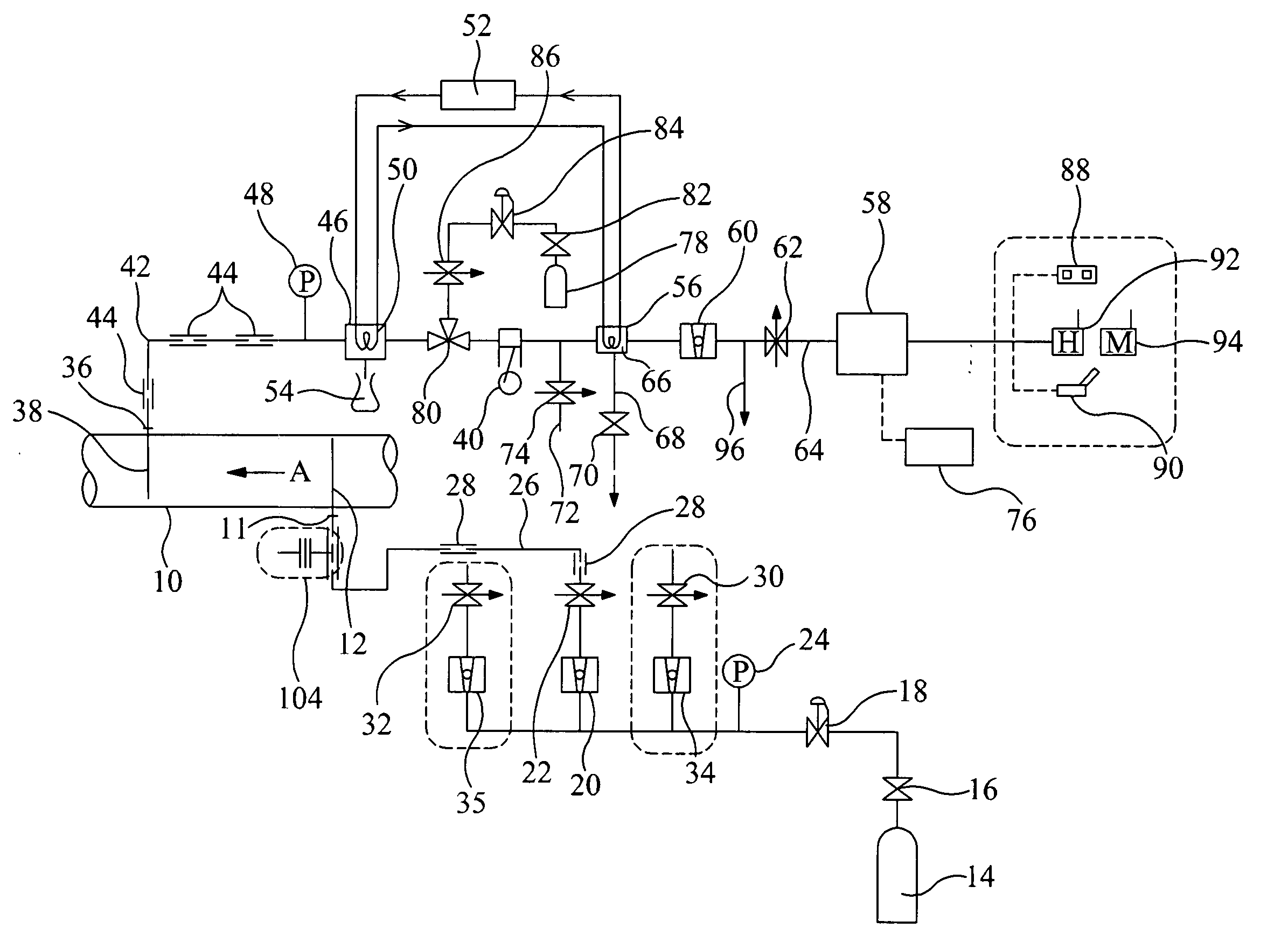
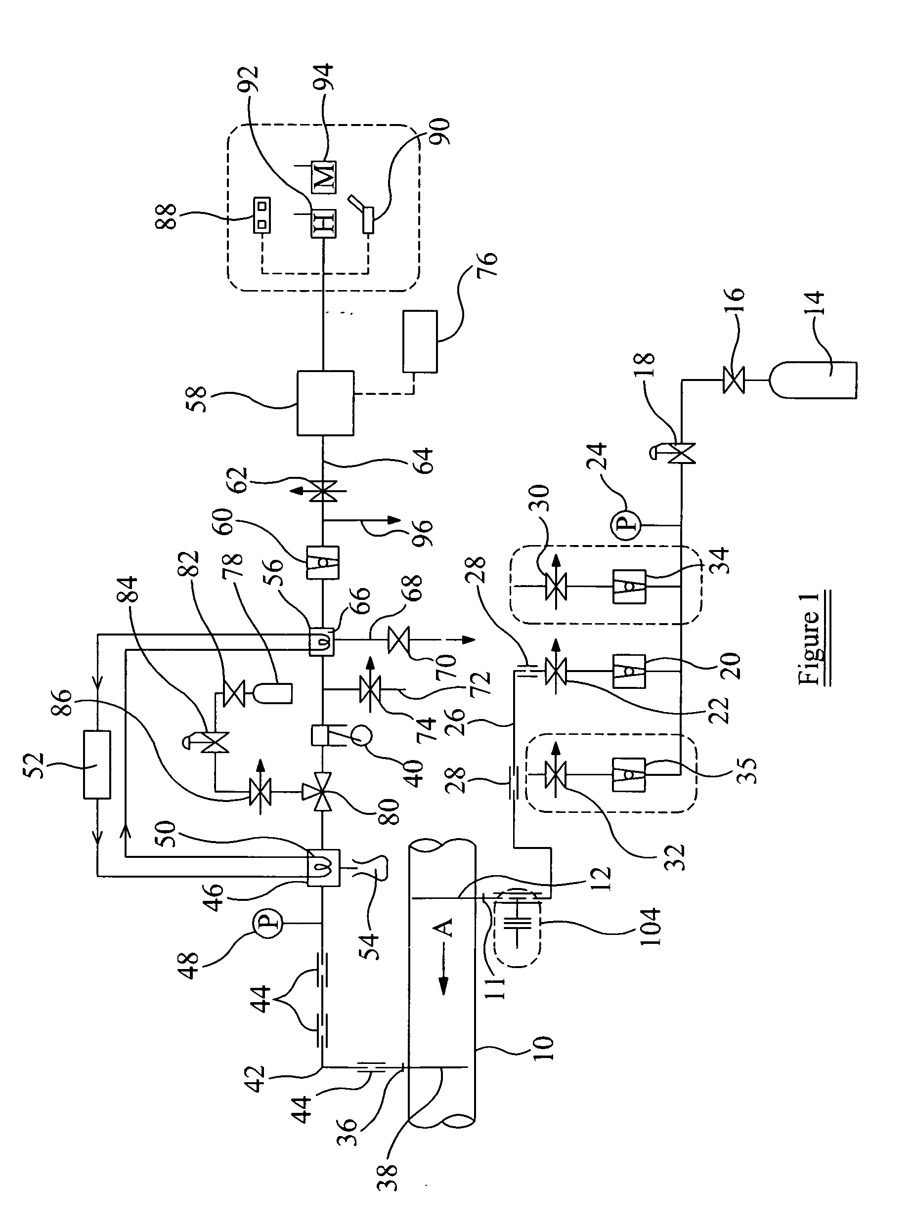
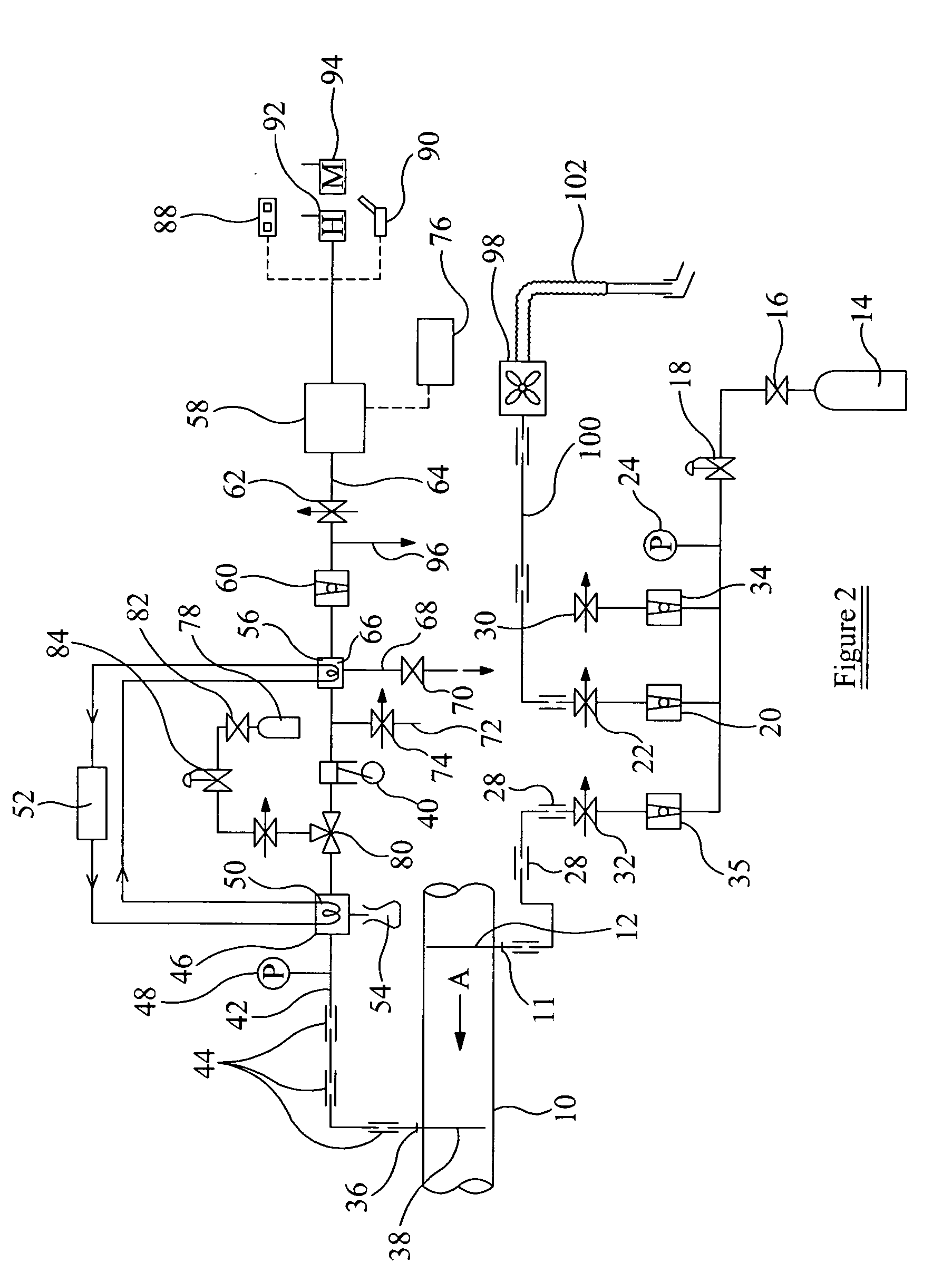
[0034]Referring to FIG. 1, the apparatus is situated at an exhaust of a steam turbine (not shown). The exhaust comprises a conduit 10 through which a mixture of an incondensable gas and a condensable gas flows in the direction indicated by the arrow A at sub atmospheric pressure. In this case, the condensable gas is steam and the incondensable gas is air. However, it will be appreciated that they could be any condensable and incondensable gas. It should also be noted that in this specification the term ‘gas’ is taken to be not only a pure gas, but may also be a mixture of gases. For example, air is a mixture of nitrogen, oxygen, argon, carbon dioxide and various other gases. The following method is used to measure the gas flow of the incondensable gas, i.e. air in this case. The system is capable of measuring the incondensable gas flow over a large range of air / steam mixture ratios from 100% air to well under 1% air.

[0035]A known quantity of a gauge gas, helium in this case, is inje...


PUM


Abstract

A method of measuring the gas flow of an incondensable gas in a flowing mixture of said incondensable gas and a condensable gas comprising the steps of calibrating a leak detector; injecting a known quantity of gauge gas at a known mass flow rate into said flowing mixture of gases; drawing a sample of the said gauge mix off at a sample point; passing said sample through a condenser so as to remove said condensable gas from the gauge mix, resulting in a test mix; passing the said test mix into the leak detector so as to measure the concentration of the gauge gas within the test mix; and calculating the mass flow rate of said incondensable gas within said flowing mixture. There is also provided a method of measuring the rate of ingress of an incondensable gas at an ingress point along a flow path of a flowing mixture of said incondensable gas and a condensable gas.

Description

RELATED APPLICATION[0001]The present application claims the priority of GB Application Serial No. 0809617.4, filed May 28, 2008. The disclosure of the aforementioned application is incorporated by reference herein in its entirety, and applicants claim the benefits of this application under 35 U.S.C. §119.BACKGROUND OF THE INVENTION[0002]This invention relates to methods of detecting leaks in a fluid flow path, particularly when said fluid comprises a mixture of a condensable gas and an incondensable gas, and more particularly still, where said fluid flow path is at the outlet to a steam turbine.[0003]Large condensing steam turbines used to produce power are responsible for producing a large proportion of the carbon dioxide emitted by the UK. As such, maximising efficiency of these turbines is very important both in terms of fuel cost to their operators and in relation to their environmental impact.[0004]Turbines work by extracting energy, in the form of heat, from a working fluid an...

Claims


Application Information

Patent Timeline
Patent Type & Authority Applications(United States)
IPC IPC(8): G01D18/00G01M3/04H01J49/26
CPCG01F1/704G01M3/30G01M3/28G01F1/74G01D21/02G01F1/34G01M3/2807G01M3/2846
Inventor NADIN, CHARLES MICHAELCOOK, DAVID
Owner WALKER ROBIN MICHAEL MR
Why Eureka
Try Eureka