Method and Apparatus for Generation of Reagent Ions in a Mass Spectrometer

a mass spectrometer and reagent ion technology, applied in the direction of instruments, particle separator tube details, separation processes, etc., can solve the problems of increasing the number of operational and design problems, the ci source filament may fail in an unpredictable manner, and the need for frequent replacemen

Active Publication Date: 2009-12-03
UNIV OF VIRGINIA ALUMNI PATENTS FOUND +1
View PDF13 Cites 22 Cited by
  • Summary
  • Abstract
  • Description
  • Claims
  • Application Information

AI Technical Summary

Benefits of technology

[0007]Embodiments of the present invention provide a reagent ion source for a mass spectrometer having a reagent vapor source that supplies gas-phase reagent molecules to a reagent ionization volume maintained at low vacuum pressure. A voltage source applies a potential across electrodes disposed in the reagent ionization volume to produce an electrical discharge (e.g., a glow discharge) that ionizes the reagent vapor to generate reagent ions. The reagent ions flow through an outlet to a reduced-pressure chamber of the mass spectrometer, and are thereafter directed to an ion trap or other structure for reaction with oppositely charged analyte ions.
[0008]In specific implementations, the reagent may take the form of a polyaromatic hydrocarbon suitable for use as an ETD reagent. The reagent vapor may be generated by heating a quantity of the reagent substance in condensed-phase form and transported to the reagent ionization volume by entrainment in a carrier gas stream. The ionization volume may be divided by an apertured partition into a discharge region extending between the electrodes and an exit region located adjacent to the outlet of the

Problems solved by technology

However, it has been found that atmospheric-pressure ionization techniques may not be well-suited to production of certain labile ETD reagent ion species, which tend to be neutralized within the environment of an atmospheric-pressure ionization chamber via loss of electrons to background gas molecules or form ion species (unsuitable for ETD) through reaction with species present in the background gas.
Mass spectrometer configurations utilizing a CI reagent ion source have been utilized successfully for ETD experiments, but p

Method used


Image

  • Method and Apparatus for Generation of Reagent Ions in a Mass Spectrometer
  • Method and Apparatus for Generation of Reagent Ions in a Mass Spectrometer
  • Method and Apparatus for Generation of Reagent Ions in a Mass Spectrometer

Examples


Embodiment Construction

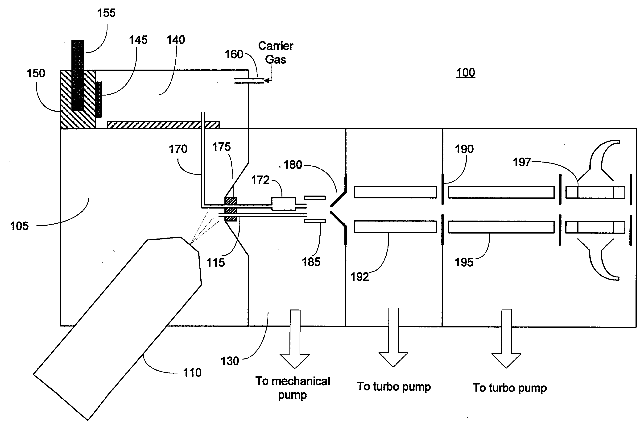
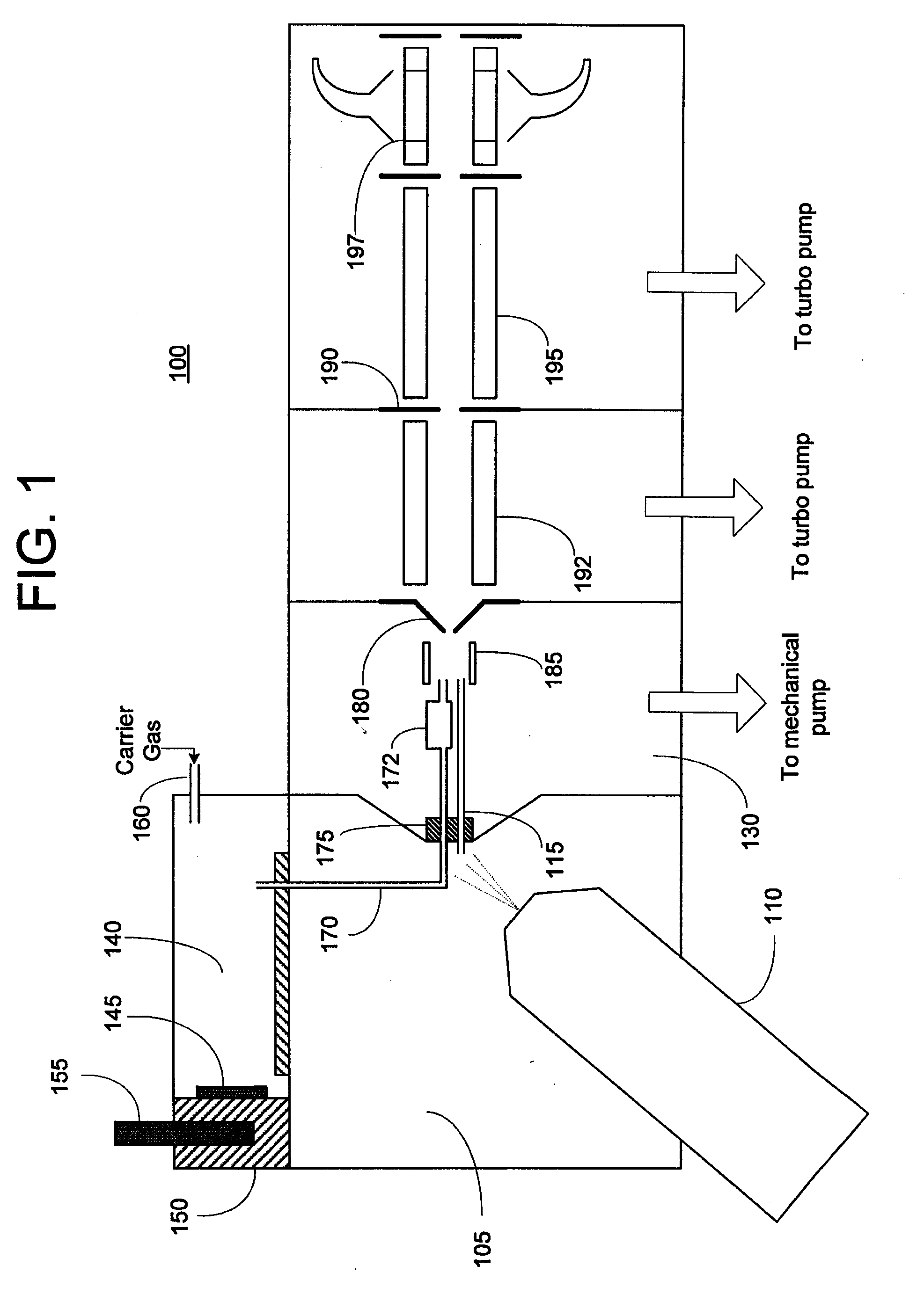
[0017]FIG. 1 schematically depicts a mass spectrometer 100 incorporating a front-end reagent ion source constructed according to an embodiment of the present invention. As used herein, the term “front-end” denotes that the ion source is configured to introduce reagent ions into a region located upstream in the analyte ion path relative to components of mass spectrometer 100 disposed in lower-pressure chambers (e.g., a mass analyzer), such that the analyte ions and reagent ions traverse a common path. Analyte ions (typically multiply-charged cations) are formed by electrospraying a sample solution into an analyte ionization chamber 105 via an electrospray probe 110. Analyte ionization chamber 105 will generally be maintained at or near atmospheric pressure. The analyte ions, together with background gas and partially desolvated droplets, flow into the inlet end of a conventional ion transfer tube 115 (which may take the form of a narrow-bore capillary tube) and traverse the length of...


PUM


Abstract

A front-end reagent ion source for a mass spectrometer is disclosed. Reagent vapor is supplied to a reagent ionization volume located within a chamber of the mass spectrometer and maintained at a low vacuum pressure. Reagent ions are formed by interaction of the reagent vapor molecules with an electrical discharge (e.g., a glow discharge) within the ionization volume, and pass into the chamber of the mass spectrometer. At least one ion optical element located along the analyte ion path transports the reagent ions to successive chambers of the mass spectrometer. The reagent ions may be combined with the analyte ions to perform ion-ion studies such as electron transfer dissociation (ETD).

Description

CROSS REFERENCE TO RELATED APPLICATION[0001]This application claims the priority benefit under 35 U.S.C. §119(e)(1) of U.S. provisional patent application Ser. No. 61 / 057,751 by Earley et al., entitled “Method and Apparatus for Generation of Reagent Ions in a Mass Spectrometer”, the disclosure of which is incorporated herein by reference.FIELD OF THE INVENTION[0002]The present invention relates generally to ion sources for mass spectrometry, and more particularly to an ion source for generating reagent ions for electron transfer dissociation or other ion-ion reaction experiments.BACKGROUND OF THE INVENTION[0003]Mass spectrometry has been extensively employed for ion-ion chemistry experiments, in which analyte ions produced from a sample are reacted with reagent ions of opposite polarity. McLuckey et al. (“Ion / Ion Chemistry of High-Mass Multiply Charged Ions, Mass Spectrometry Reviews, Vol. 17, pp. 369-407 (1998)) discusses various examples of mass spectrometric studies of this type....

Claims


Application Information

Patent Timeline
IPC IPC(8): B01D59/44H01J49/00H01J27/00
CPCH01J49/12H01J49/0095H01J49/0072
Inventor SHABANOWITZ, JEFFREYCOMPTON, PHILIP D.EARLEY, LEESTAFFORD, JR., GEORGE C.HUNT, DONALD F.MULLEN, CHRISTOPHER
Owner UNIV OF VIRGINIA ALUMNI PATENTS FOUND
Why Eureka
Try Eureka