
Cooling fin and package substrate comprising the cooling fin and manufacturing method thereof

Inactive Publication Date: 2009-12-03
SAMSUNG ELECTRO MECHANICS CO LTD
View PDF1 Cites 9 Cited by
  • Summary
  • Abstract
  • Description
  • Claims
  • Application Information

AI Technical Summary

Benefits of technology

[0013]Furthermore, the present invention provides a cooling fin, which may be manufactured a simple process of injecting fireable paste containing carbon nanotubes or carbon nanofiber, and a method of manufacturing the cooling fin.
[0014]Furthermore, the present invention provides a package substrate, which may be manufactured by attaching a cooling fin having an improved cooling performance to the package substrate, and a method of manufacturing the package substrate.
[0015]Furthermore, the present invention provides a package substrate, which includes a cooling fin that is configured to have a cover structure to improve a cooling performance, and which shields a printed circuit board including a semiconductor chip from an external environment in a sealing manner, thus obviating an additional resin encapsulation, and a method of manufacturing the package substrate.
[0025]The firing the cooling object may cause the resin layer and the binder to be eliminated.
[0031]The firing the cooling object may cause the resin layer and the binder to be eliminated.

Problems solved by technology

However, as the number of their mounting and packaging are increased, power consumption and heat generation are increased, thus exerting a bad influence on reliability of products and on their attractiveness to customers.
If chemical vapor deposition is used, although it is possible to grow the carbon nanotubes in a vertical direction, it is impossible to enable the carbon nanotubes to have various structures.
Thus, there is a limit to the production of cooling fins whose high cooling performance is due to an increase in the surface area of the cooling fins.
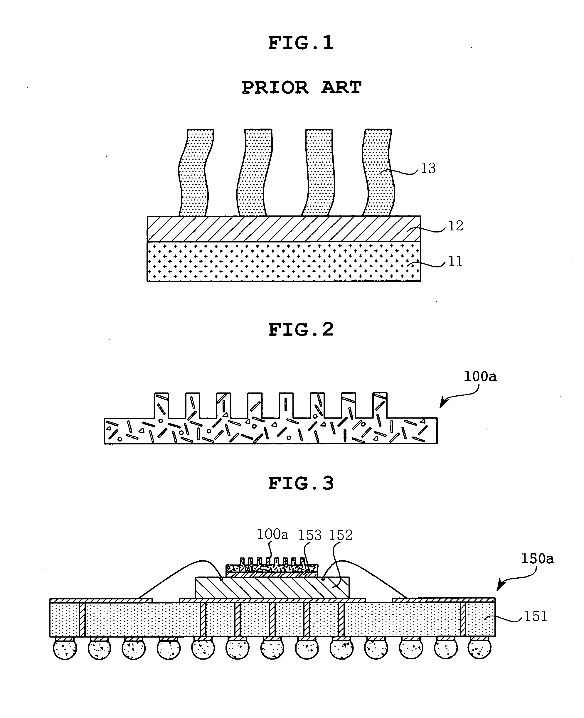
Further, since the chemical vapor deposition process must be conducted at a relatively high temperature ranging from 500° C. to 1000° C., the base material from which the carbon nanotubes can be grown is disadvantageously restricted to ones which can be used at the high temperature, for example, the silicon substrate 11, as illustrated in FIG. 1.
Furthermore, the conventional process is disadvantageous in that there are needs for a separate metal catalyst 12 adapted to grow the carbon nanotube as well as a special container having a high hermetic performance regarding forming a nano-sized metal catalyst 12 on the silicon substrate 11, thus increasing equipment costs.

Method used


Image

  • Cooling fin and package substrate comprising the cooling fin and manufacturing method thereof
  • Cooling fin and package substrate comprising the cooling fin and manufacturing method thereof
  • Cooling fin and package substrate comprising the cooling fin and manufacturing method thereof

Examples


Embodiment Construction

[0040]Hereinafter, preferred embodiments of the present invention will be described in greater detail with reference to the accompanying drawings.

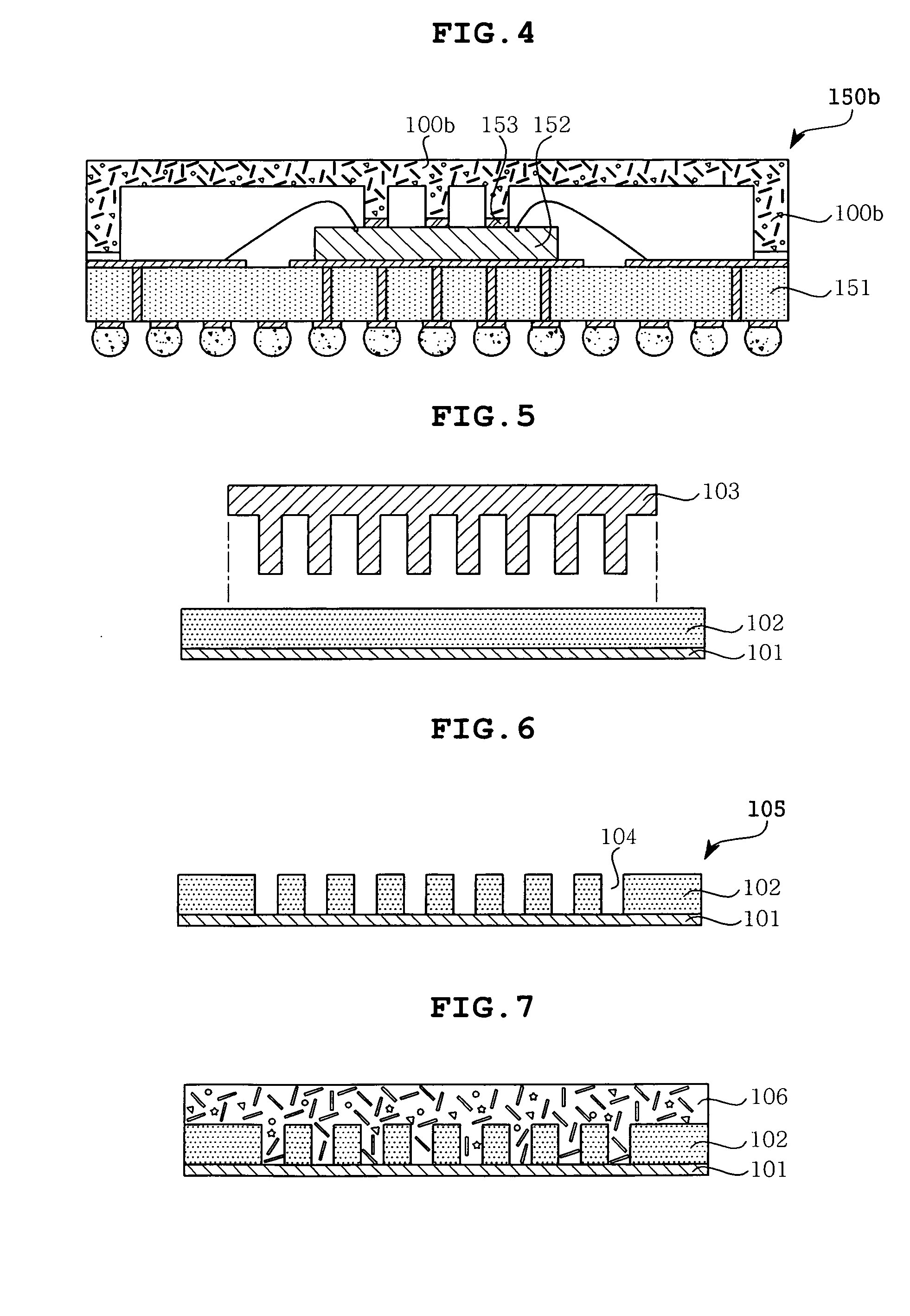
[0041]FIG. 2 is a cross-sectional view showing a cooling fin according to a preferred embodiment of the present invention, FIG. 3 is a cross-sectional view showing a package substrate including a cooling fin, according to a preferred embodiment of the present invention, FIG. 4 is a cross-sectional view showing a package substrate including a cooling fin, according to another embodiment of the present invention, and FIGS. 5 to 7 are cross-sectional views showing a method of manufacturing a cooling fin, according to an embodiment of the present invention.

[0042]Referring to FIG. 2, a cooling fin 100a according to an embodiment of the present invention is now described.

[0043]In this embodiment of the present invention, the cooling fin 100a is distinctively comprised of a fired object containing a carbon component. In this embodiment, the fired...


PUM


Abstract

Disclosed herein is a cooling fin, which is excellent in cooling performance and is simply manufactured, a package substrate comprising the cooling fin, and a manufacturing method thereof. Fireable paste containing a carbon component is applied into grooves of a mold, thus forming a cooling fin having a pattern corresponding to the grooves. Thus, it enables the production of cooling fins having various configurations, thus improving a cooling performance of a package substrate incorporating the cooling fin.

Description

CROSS REFERENCE TO RELATED APPLICATION[0001]This application claims the benefit of Korean Patent Application No. 10-2008-51003, filed May 30, 2008, entitled “COOLING FIN AND PACKAGE SUBSTRATE COMPRISING THE COOLING FIN AND FABRICATING METHOD OF THE SAME”, which is hereby incorporated by reference in its entirety into this application.BACKGROUND OF THE INVENTION [0002]1. Field of the Invention[0003]The present invention relates generally to a cooling fin and a package substrate comprising the cooling fin and a manufacturing method thereof, and, more particularly, to a cooling fin, which is excellent in cooling performance and is simply manufactured, a package substrate comprising the cooling fin, and a manufacturing method thereof.[0004]2. Description of the Related Art[0005]These days, in response to miniaturization and the widening of the functionality of electronic products, more passive / active devices and semiconductor chips (IC) are mounted in the electronic products and package...

Claims


Application Information

Patent Timeline
IPC IPC(8): H01L23/467F28F7/00H01L21/58B21D53/02
CPCC04B35/80Y10T29/49002C04B2235/3418C04B2235/407C04B2235/408C04B2235/5288F28F3/02F28F21/02H01L23/373H01L2224/16H01L2224/48091H01L2224/48227H01L2924/15311H01L2924/3025C04B2235/3217Y10T29/4935H01L24/48B82Y30/00H01L2924/00014C04B35/52H01L2924/1815H01L2224/45099H01L2224/45015H01L2924/207H01L23/34H05K7/20
Inventor LEE, EUNG SUEKYOO, JE GWANGRYU, CHANG SUPHWANG, JUN OHPARK, JUN HEYOUNGMOK, JEE SOO
Owner SAMSUNG ELECTRO MECHANICS CO LTD
Learn More