
Semiconductor integrated circuit and operation method for the same

a technology of integrated circuits and integrated circuits, applied in pulse generators, instruments, pulse techniques, etc., can solve the problems of increasing the lsi of standby leakage current of mos transistors of the system, increasing the threshold voltage of mos transistors, and mos transistors that exhibit low threshold voltages. , to achieve the effect of increasing the threshold voltage and increasing the standby leakage curren

Active Publication Date: 2009-12-03
RENESAS ELECTRONICS CORP
View PDF3 Cites 35 Cited by
  • Summary
  • Abstract
  • Description
  • Claims
  • Application Information

AI Technical Summary

Benefits of technology

The present invention provides a semiconductor integrated circuit with a built-in temperature detection circuit and a functional module of a large operating current. The circuit can perform precise and safe control of chip temperature, while being little influenced by noise from the system board. The technical effect of the invention is to improve the accuracy and performance of the semiconductor integrated circuit, especially in the case of on-vehicle navigation systems where the chip is mounted.

Problems solved by technology

Keeping pace with the miniaturization of a semiconductor integrated circuit, a recent MOS transistor tends to exhibit low threshold voltage and increased standby leakage current.
However, the standby leakage current of an MOS transistor of the system LSI increases in exponential proportion to the temperature rise.
), a vicious iteration between the increase in the standby leakage current and the rise of the chip temperature of LSI repeats endlessly, starts a thermal runaway, and finally leads to a thermal destruction of the chip of the system LSI.
When a thermal runaway starts, even if the operation clock frequency of a built-in CPU is decreased, the chip temperature of the system LSI cannot be reduced, and it becomes very difficult to break the vicious iteration between the increase in the leakage current and the rise of the chip temperature.

Method used


Image

  • Semiconductor integrated circuit and operation method for the same
  • Semiconductor integrated circuit and operation method for the same
  • Semiconductor integrated circuit and operation method for the same

Examples


embodiment

Explanation of Embodiment

[0080]Next, an embodiment is explained further in full detail. In the entire diagrams for explaining the best mode for the embodiment of the present invention, the same symbol is attached to a component which has the same function as in the previous drawing, and the repeated explanation thereof is omitted.

[0081]>

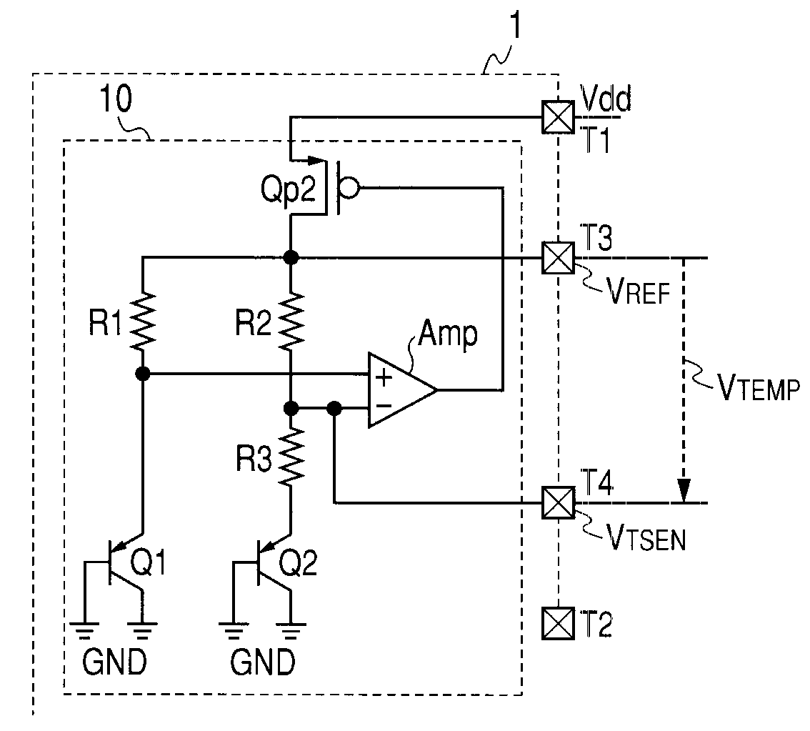
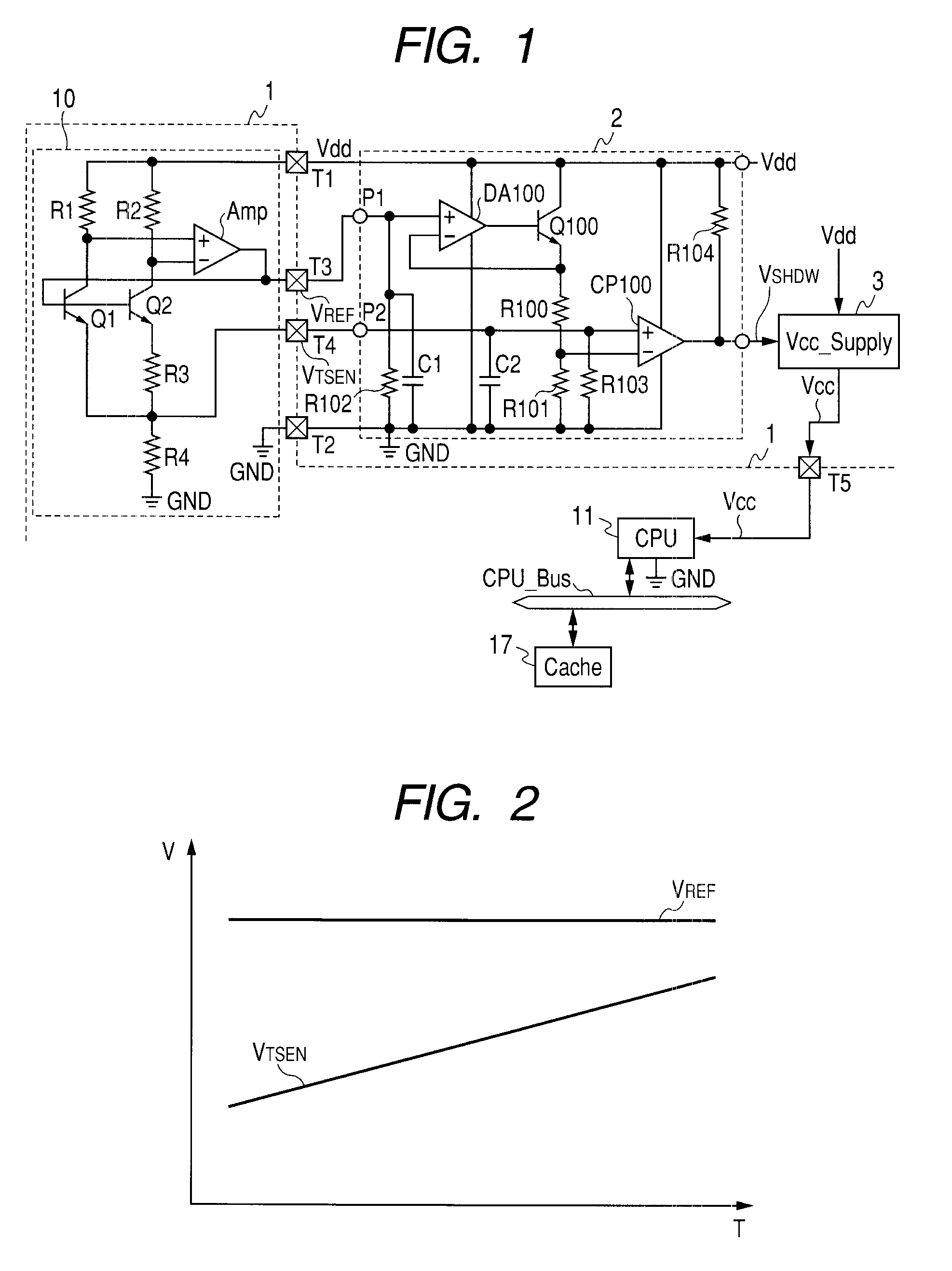
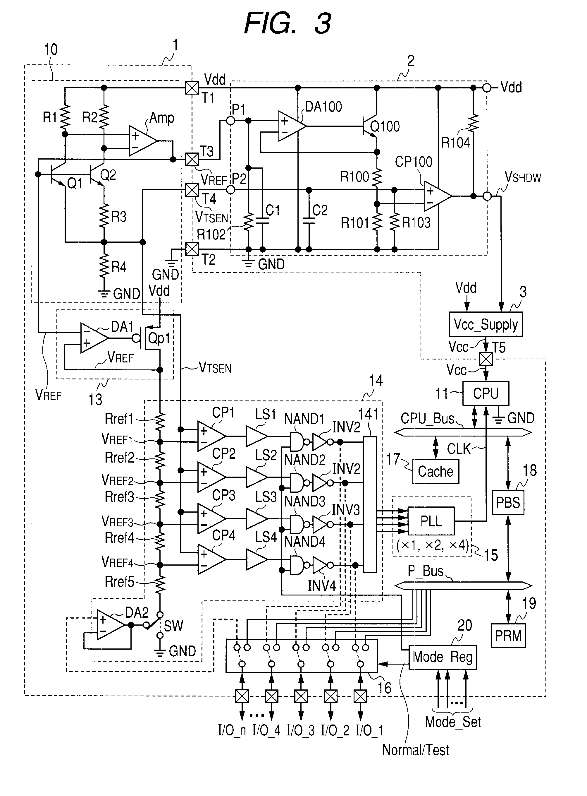
[0082]FIG. 1 illustrates configuration of a system board in which a semiconductor integrated circuit 1, an over-temperature control circuit 2, and a power supply circuit 3 are mounted as a system LSI, according to an embodiment of the present invention. That is, the system board illustrated in FIG. 1 is required for high reliability, as in a system board for use in an on-vehicle car-navigation system. The semiconductor integrated circuit 1 is a microcomputer for use in the car navigation system, and includes internal circuits such as a temperature detection circuit 10 which detects the temperature of a chip, a central processing unit (CPU) 11, and a ...


PUM


Abstract

The semiconductor integrated circuit is provided, in which an external temperature control or temperature monitoring is possible, with little influence by the noise of a system board which mounts the semiconductor integrated circuit. The semiconductor integrated circuit includes the temperature detection circuit which detects the chip temperature, and the functional module which flows a large operating current. An external terminal which supplies operating voltage, and an external terminal which supplies ground voltage are coupled to the functional module. The temperature detection circuit generates a temperature detection signal and a reference signal. The reference signal and the temperature detection signal are led out to the exterior of the semiconductor integrated circuit via a first external output terminal and a second external output terminal, respectively, and are supplied to an external temperature control / monitoring circuit which has a circuitry type of a differential amplifier circuit.

Description

CROSS-REFERENCE TO RELATED APPLICATIONS [0001]The disclosure of Japanese Patent Application No. 2008-137778 filed on May 27, 2008 including the specification, drawings and abstract is incorporated herein by reference in its entirety.BACKGROUND OF THE INVENTION[0002]The present invention relates to a semiconductor integrated circuit and an operation method for the same, in particular, to technology which is useful for performing temperature control or temperature monitoring outside a semiconductor integrated circuit which has a built-in functional module with a large operating current and a built-in temperature detection circuit to detect chip temperature and which is influenced greatly by the noise of a system board.[0003]Document 1 in the following describes the outline of a semiconductor integrated circuit working as a precision digital thermometer (product name MAX1617) which reports the temperature of both a remote sensor and its own package. A diode-connected transistor as a re...

Claims


Application Information

Patent Timeline
Patent Type & Authority Applications(United States)
IPC IPC(8): H01L35/00H10N10/00
CPCG05F3/30G05F3/227
Inventor KAMEYAMA, TADASHIITO, TAKAYASUSAITO, SEIICHISATO
Owner RENESAS ELECTRONICS CORP
Learn More