Film laminating apparatus

a film laminating and film technology, applied in non-linear optics, instruments, other domestic objects, etc., can solve the problems of large film laminating apparatuses, difficult to introduce film laminating apparatuses directly, etc., to improve the quality of glass production, simplify the construction of nip roller units, and make lighter

Inactive Publication Date: 2009-12-10
CORNING INC
View PDF4 Cites 11 Cited by
  • Summary
  • Abstract
  • Description
  • Claims
  • Application Information

AI Technical Summary

Benefits of technology

[0015]The film laminating apparatus of the present invention comprises the vertical nip roller units, each of which comprises the plurality of nip rollers, wherein each nip roller has a vertically oriented rotational axis, and the nip rollers of the nip roller units are pressed, via the films respectively fed from the film feed units, against both surfaces of the glass sheets, which are being conveyed horizontally in an upright orientation by the conveyor. This configuration enables the film laminating apparatus to be directly introduced into the manufacturing line of the glass sheets such that it can continuously laminate films onto both surfaces of the glass sheets. This provides the advantage that the manufacturing plant can accommodate increases in glass production quantity per unit time without delay.
[0016]In addition, the nip roller unit itself can perform the film laminating operation with the position of the entirety thereof being fixed. The nip roller unit is provided in an upright manner such that the rotational axes of the respective nip rollers provided therein are vertically oriented. This provides the advantages that the construction of the nip roller unit can be simplified and made lighter, and the space occupied by the apparatus can be significantly reduced. In addition, the need to reduce cycle times for the glass production process with increases in the quantity of produced glass can be satisfied.
[0017]Further, rotating the nip rollers and the film feed roll in each nip roller unit in synchronization with each other precludes the possibility of a wrinkle or the like occurring in the film laminated on the surface of the glass sheets.
[0018]Still further, the film laminating apparatus of the invention has an automatic film roll replacement mechanism. This provides the advantages that replacement of the film rolls can be performed in a very short time, and that the need to reduce the cycle time of the glass production process can be satisfied without loss of glass.

Problems solved by technology

However, in the case that protective films are automatically and simultaneously laminated on both surfaces of glass sheets having comparatively large areas, large film laminating apparatuses are required.
Further, it is difficult to introduce film laminating apparatuses directly that is, in line, in a downstream part of glass sheet manufacturing lines.

Method used


Image

  • Film laminating apparatus
  • Film laminating apparatus
  • Film laminating apparatus

Examples


Embodiment Construction

[0034]Hereinafter, the constitution and operation of a preferred embodiment of the invention will be described in detail with reference to the accompanying drawings.

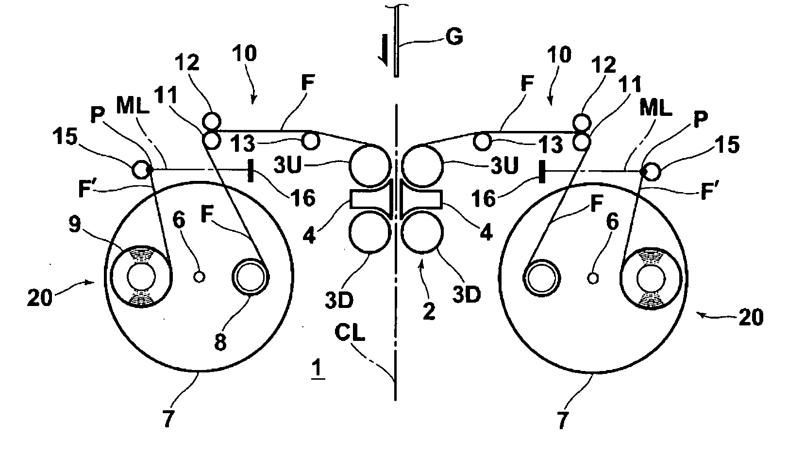
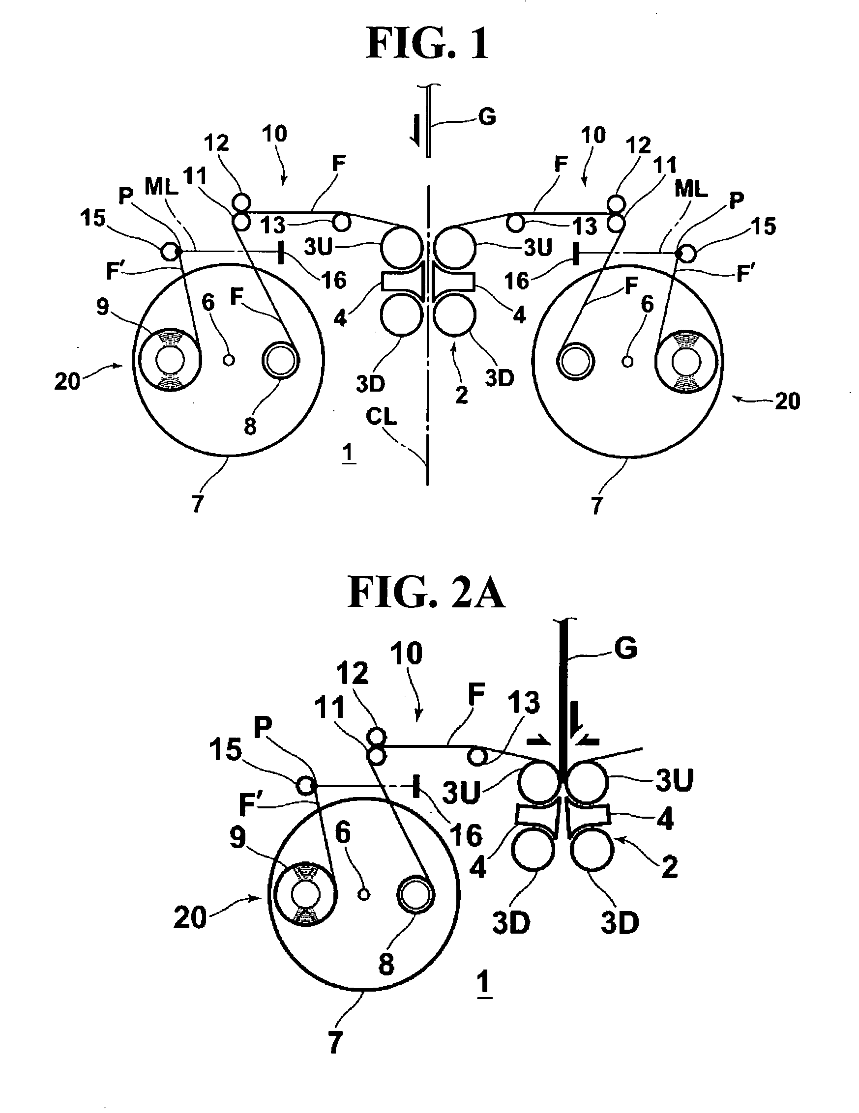
[0035]FIG. 1 is a plan view that schematically illustrates a film laminating apparatus according to an embodiment of the invention.

[0036]Referring to FIG. 1, a film laminating apparatus 1 comprises a vertical air-float conveyor (not shown) for horizontally conveying glass sheets G on air cushions parallel with the surfaces of the glass sheet G while supporting the lower end of the glass sheets G with the glass sheets G being held in an upright orientation. The film laminating apparatus 1 is formed symmetrically with respect to a center line CL which is a conveyance path, along which the glass sheet G is conveyed by the conveyor.

[0037]In the film laminating apparatus 1, a vertical nip roller unit 2 including a pair of nip rollers 3U (disposed upstream) and 3D (disposed downstream) is provided on each side of the center li...


PUM

PropertyMeasurementUnit
areaaaaaaaaaaa
areasaaaaaaaaaa
conveying speedaaaaaaaaaa

Abstract

A conveyor conveys glass sheets horizontally, while holding them in an upright orientation. Film feed units are provided on both sides of a conveyance path of the glass sheets. Nip rollers press against both surfaces of the glass sheets via films fed from the film feed units so as to sandwich the glass sheets, while the glass sheets are being conveyed by the conveyor.

Description

TECHNICAL FIELD[0001]The present invention relates to a film laminating apparatus. Particularly, the present invention relates to a film laminating apparatus for simultaneously laminating protective films on both surfaces of comparatively large-area glass sheets, which are manufactured as LCD glass substrates or the like in factories, prior to being cut into smaller plates according to the specific uses thereof.BACKGROUND ART[0002]In factories that manufacture glass sheets which are used, for example, as LCD glass substrates, protective films are laminated on both surfaces of a manufactured glass sheet at the final stations of transportation conveyors for conveying the manufactured glass sheets. The purpose of the protective films is to protect the glass surface quality during subsequent glass handling processes.[0003]Typically, when such a protective film is laminated on the surfaces of a glass sheet, a press roller is used to laminate thereon the protective film unwound from a fil...

Claims


Application Information

Patent Timeline
Patent Type & Authority Applications(United States)
IPC IPC(8): B32B37/02
CPCB29C63/0013B29C63/02B32B17/10018B32B17/10935B32B17/10954B32B37/12Y10T156/1317B32B38/0004B32B2315/08B32B2457/20B32B2457/202C03C2218/355B32B37/226B29L2031/3475B32B43/00G02F1/13G02F1/1333
Inventor NAGURA, TAKAYUKI
Owner CORNING INC
Why Eureka
Try Eureka