
Flat cable for mounted display devices

a technology for display devices and flat cables, applied in the field of flat cables for mounted display devices, can solve the problems of difficult and relatively technical and expensive passage through hdmi cables, like routing ac power, and the hdmi cable hanging from a mounted television set is neither decorative nor practical, and achieves the effect of reducing parasitic capacitan

Inactive Publication Date: 2009-12-10
SONY CORP +1
View PDF5 Cites 22 Cited by
  • Summary
  • Abstract
  • Description
  • Claims
  • Application Information

AI Technical Summary

Benefits of technology

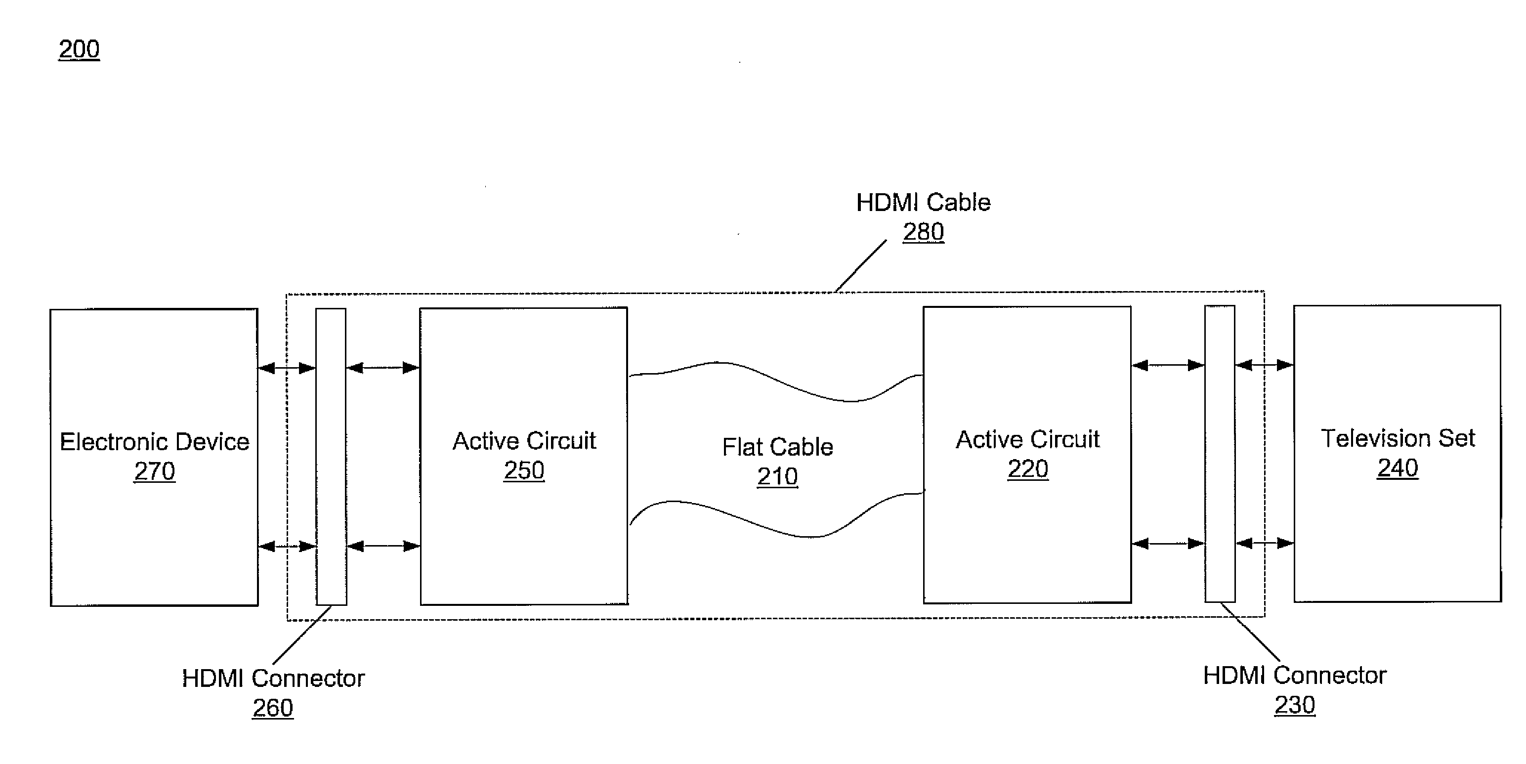
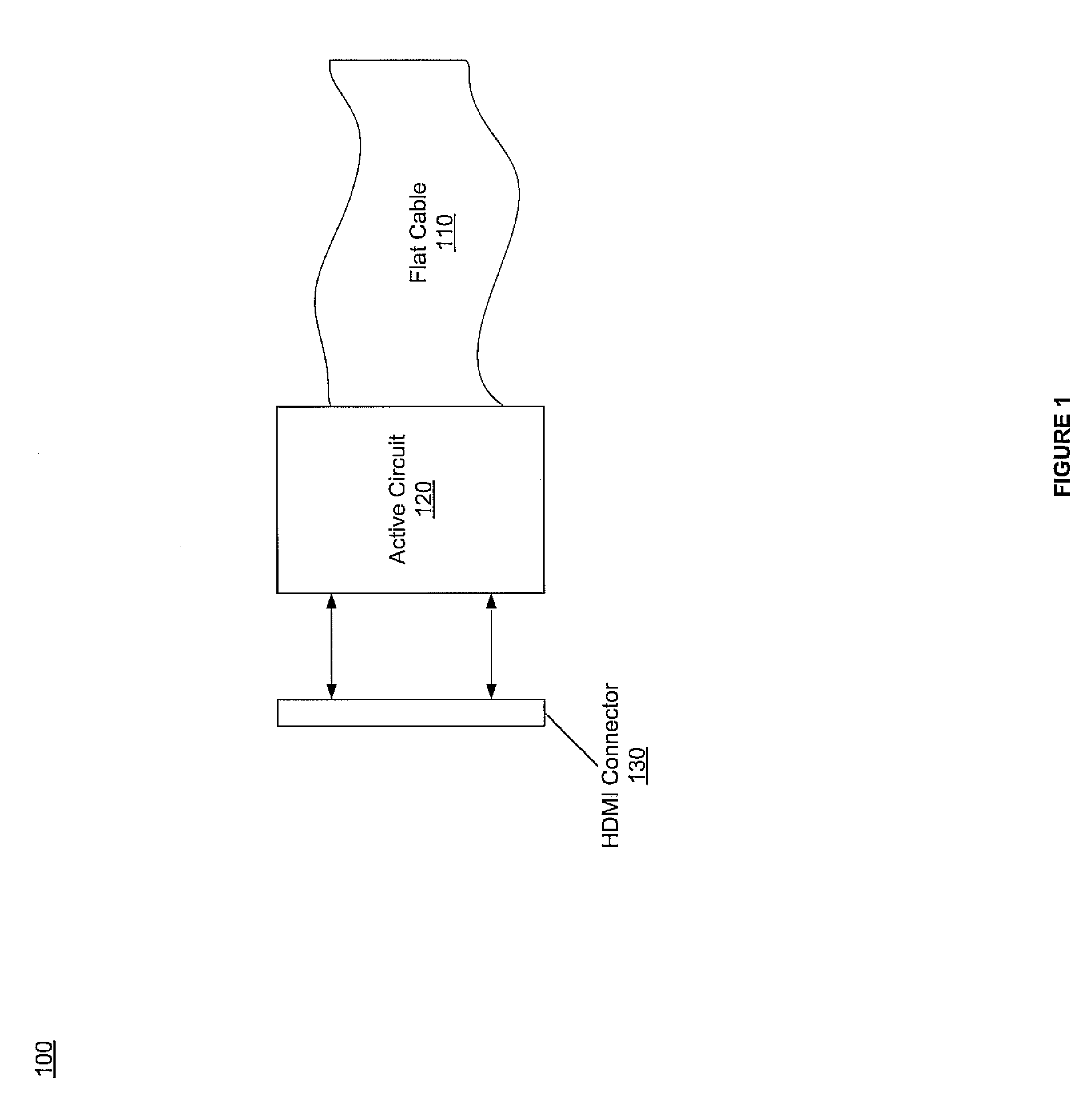
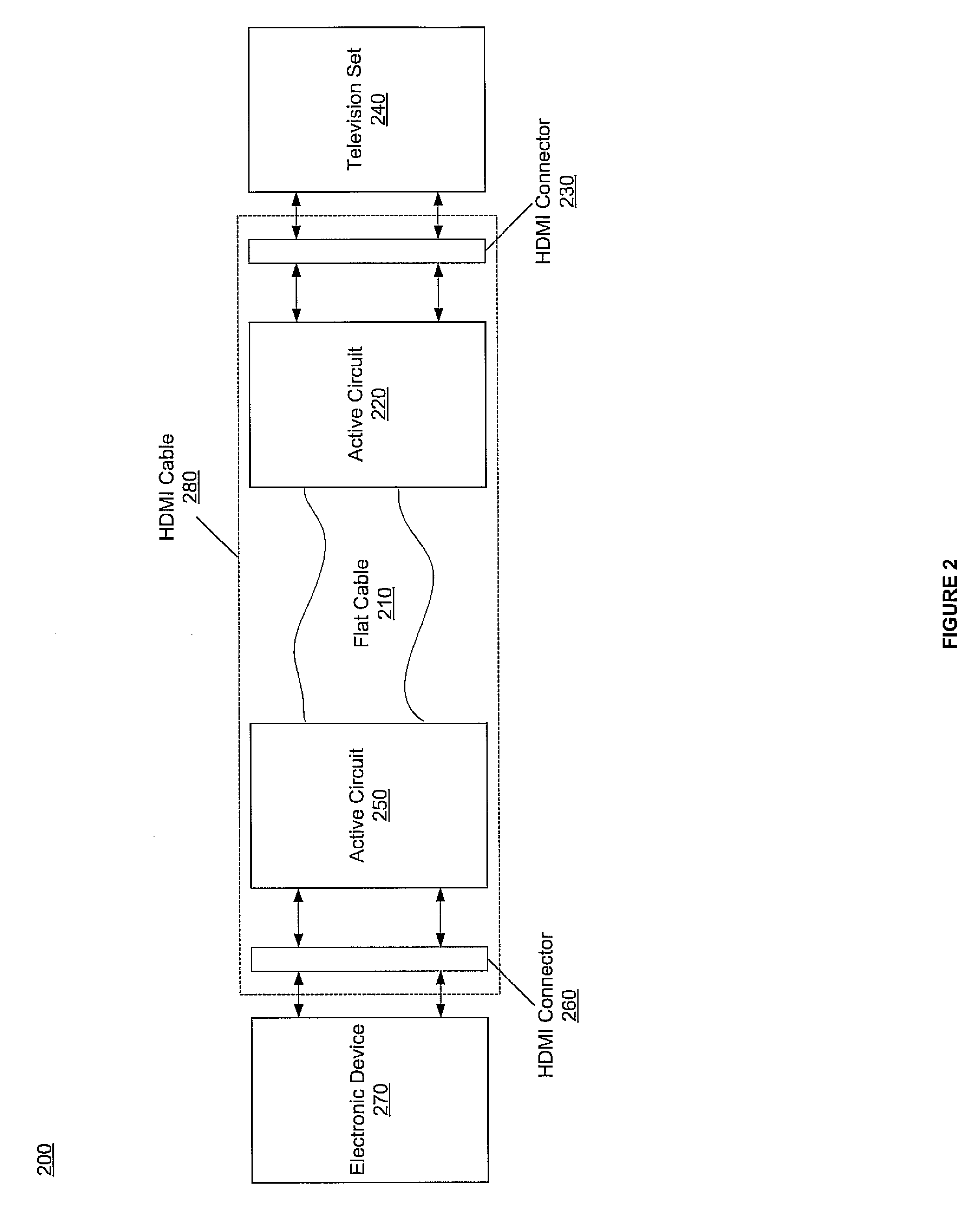
[0015]In one embodiment, isolation is performed via an active circuit. In one exemplary embodiment, isolation may cause the flat cable to appear shorter than its actual length during HDMI compliance testing, e.g., impedance testing. In one embodiment, isolation may cause CEC, DDC and TMDS lines to actively terminate for reducing parasitic capacitance from the leng

Problems solved by technology

Moreover, passing through an HDMI cable, like routing AC power, is difficult and relatively technical and expensive.
Unfortunately, HDMI cables are large and visible, e.g., some cables are 5-6 mm in diameter.
Thus, when an HDMI cable is connected to a television set mounted on a wall, the HDMI cable is visible, hard to conceal and hangs down from the side of the wall as it connects to another electronic device, e.g., receiver, DVD player, etc.
An HDMI cable hanging from a mounted television set is neither decorative nor practical.
For example, controlling the attenuation and impedance become very difficult in a flattened cable.
Thus, flattening an HDMI cable, while possible, makes it challenging for the HDMI cable to pass HDMI compliance tests.
The eye pattern test may also show the rising and failing edges of digital bits that do not always occur at the same time, thereby leading to timing jitter.
In other words, if the signal collapses in either the vertical direction or the horizontal direction, the signal is lost.
Unfortunately, while wireless HDMI may provide communication wirelessly and eliminate the visible cable, it is expensive to implement.
Thus, wireless HDMI is not readily used by a wide range of consumers.

Method used


Image

  • Flat cable for mounted display devices
  • Flat cable for mounted display devices
  • Flat cable for mounted display devices

Examples


Embodiment Construction

[0021]Reference will now be made in detail to embodiments of the present invention, examples of which are illustrated in the accompanying drawings. While the invention will be described in conjunction with these embodiments, it will be understood that they are not intended to limit the invention to these embodiments. On the contrary, the invention is intended to cover alternatives, modifications and equivalents, which may be included within the spirit and scope of the invention as defined by the appended claims. Furthermore, in the following detailed description of the present invention, numerous specific details are set forth in order to provide a thorough understanding of the present invention. However, it will be evident to one of ordinary skill in the art that the present invention may be practiced without these specific details. In other instances, well known methods, procedures, components, and circuits have not been described in detail as not to unnecessarily obscure aspects ...


PUM


Abstract

A flat high definition multimedia interface (HDMI) cable. The flat cable that is less visible in comparison to a round HDMI cable for wall mounted television setup. An HDMI connector is coupled to the flat cable. An active circuit isolates physical characteristics of the HDMI connector. The active circuit causes the flat cable to appear shorter than its actual length during HDMI compliance testing using impedance testing. Moreover, the active circuit causes a consumer electronic control (CEC) line, a display data channel (DDC) line and transition minimized differential signal (TMDS) line to actively terminate for reducing parasitic capacitance from the length of the flat cable during HDMI compliance testing. Thus, the isolation allows the flat cable to satisfy HDMI compliant testing. The flat cable may be selected from a group consisting of ribbon cable, twisted pair cable, flexible printed circuit board, micro coax cable, optical cable and glass fiber cable.

Description

TECHNICAL FIELD[0001]Embodiments of the present invention relate to the field of electronics. More particularly, embodiments of the present invention relate to a cable for supplying signals to a mounted display device.BACKGROUND ART[0002]With advent of flat screen televisions, more and more consumers are utilizing flat screen televisions not only for their excellent picture quality but also because they are less bulky and more decorative. As a result, many consumers mount their television sets on a wall, for example above a fireplace, etc.[0003]In general, flat screen televisions have high definition multimedia interface (HDMI) capability. HDMI facilitates uncompressed digital signals for the highest picture and sound quality. Moreover, the HDMI cable provides one common cable for video, audio and control signals and enables communication and control between electronic devices instead of having individual and separate cables for video, audio and control signals, etc. Additionally, H...

Claims


Application Information

Patent Timeline
IPC IPC(8): H01B7/08
CPCH01B7/08
Inventor SHINTANI, PETER
Owner SONY CORP
Learn More