
Multiphase grid synchronized regulated current source inverter systems

a current source inverter and multi-phase grid technology, applied in ac network circuit arrangements dc-ac conversion without reversal, etc., can solve the problem of pva representing a dc source with a degree of unpredictability in terms of output stability, requiring high-speed semiconductor devices that are limited, and affecting the magnitude of dc output voltage. the effect of three-phase current total harmoni

Active Publication Date: 2009-12-10
ALENCON ACQUISITION
View PDF11 Cites 55 Cited by
  • Summary
  • Abstract
  • Description
  • Claims
  • Application Information

AI Technical Summary

Benefits of technology

[0018]For a power conversion system of the present invention with conversion of dc power from a wind power generated source, at least one wind-generated power collection node is provided with the output of the collection node connected to multiple regulated current source inverters. Each inverter has a plurality of switching devices for producing a multiple phase ac output. The multiple phase ac output of each inverter operates synchronously with the voltages of the electric power grid. Commutation of the switching devices in each inverter is sequenced to produce multiple phase ac output currents from each inverter. The wind-generated power collection node may be at least one turbine driven ac generator having a rectified dc output. At least one transformer for phase shifting the multiple phase ac output currents from all of the inverters is provided to produce a supply of three-phase currents for injection into the electric power grid. Each of the three-phase currents has a multiple stepped waveform. Increasing the number of inverters in an embodiment of the present invention increases the number of multiple steps in the waveform of each of the three-phase current and decreases the total harmonic distortion of the three-phase currents.

Problems solved by technology

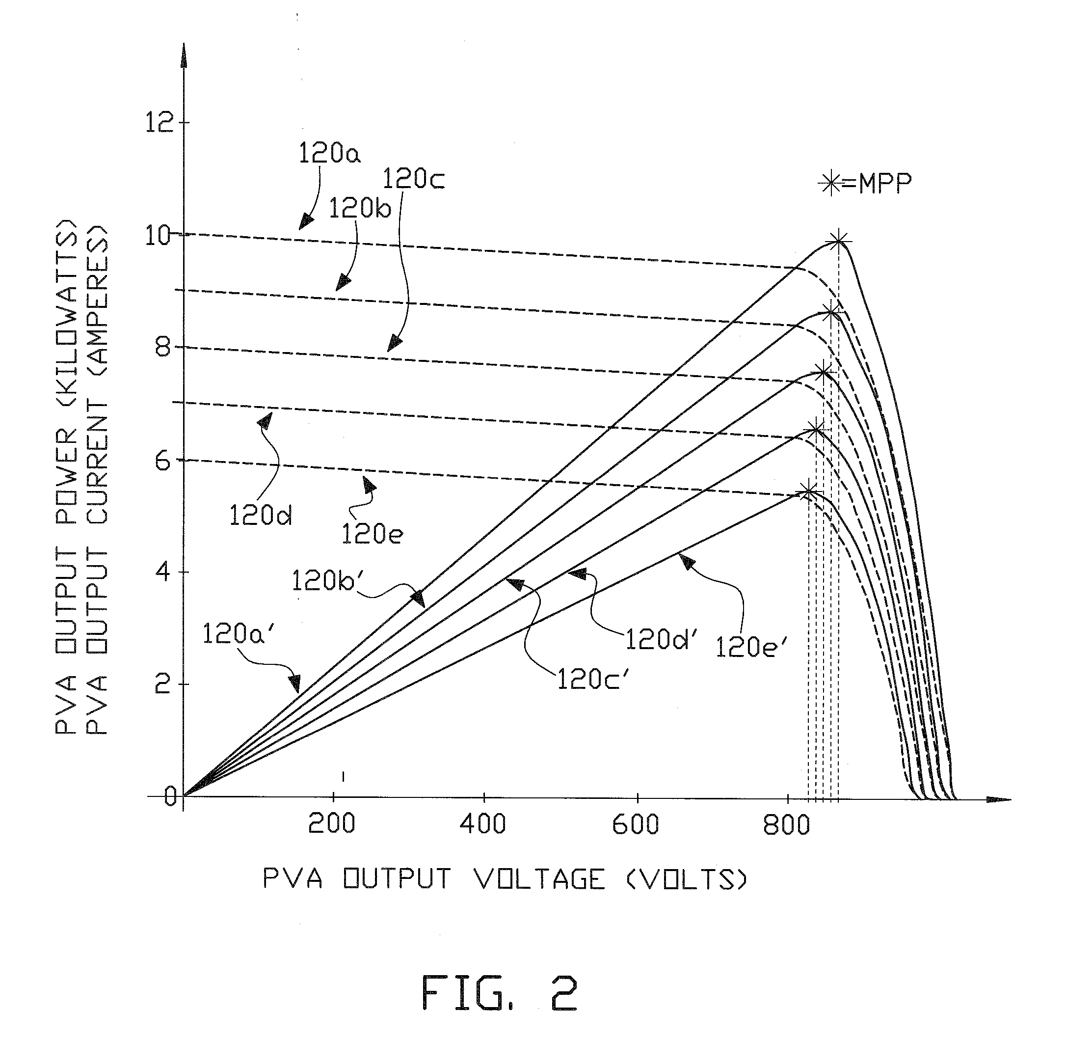
Additionally the level of current demand from the output of the PVA directly affects the magnitude of the dc output voltage.
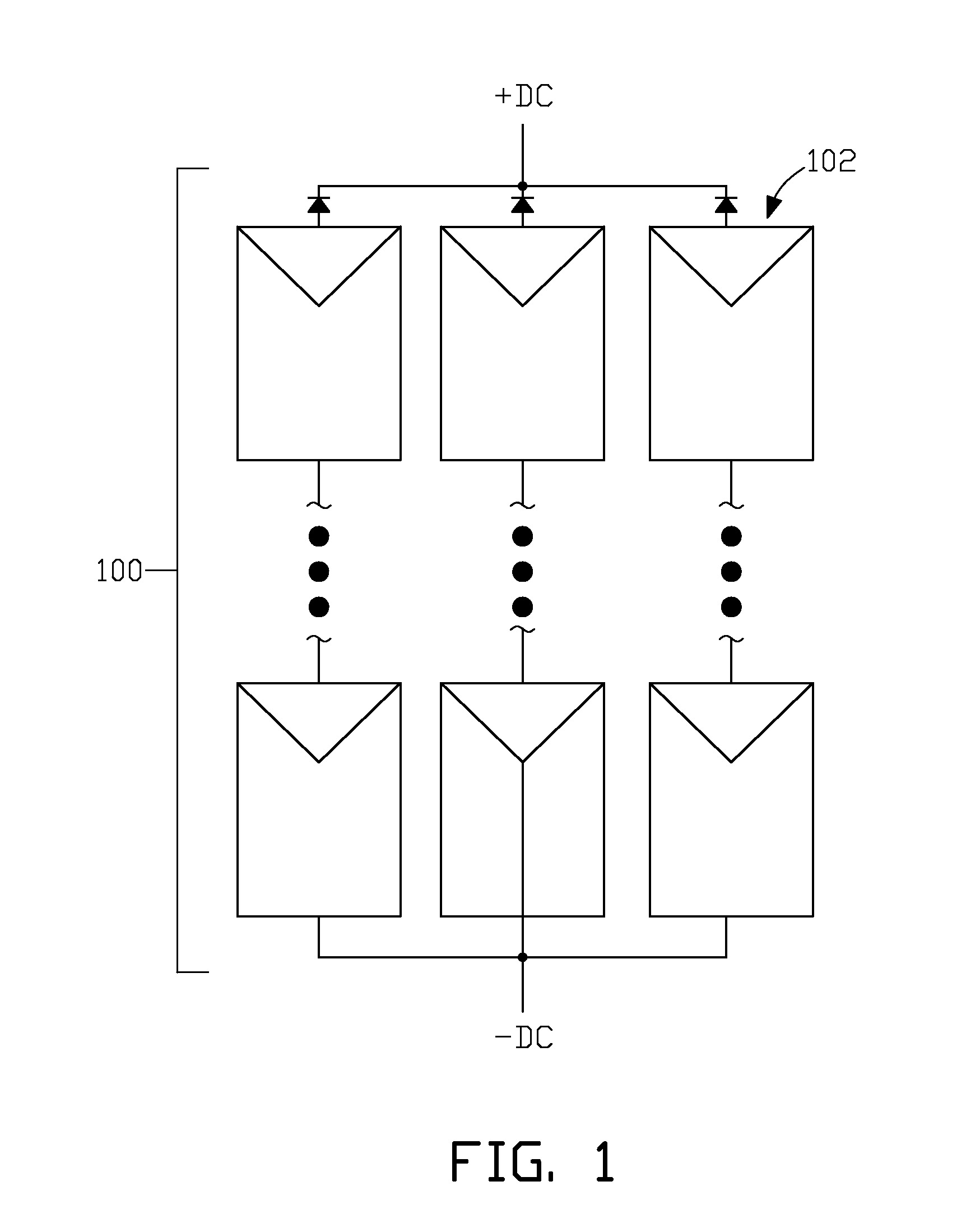
Generally then, a PVA represents a dc source having a degree of unpredictability in terms of output stability since the output is a function of instantaneously uncontrollable factors such as the instantaneous level of incident sunlight or ambient temperature.
They are switched (commutated) at a high rate, which requires high speed semiconductor devices that are limited in steady state current carrying capacity and power dissipation.
Switching losses are the limiting factor for the amount of power that can be converted by this type of inverter.
Although switch mode voltage source inverters are widely used in residential and some commercial solar power converters that are capable of generating power levels up to 500 kW, they are too small to be successfully used in multi-megawatt ranges needed for large solar farm customers.
The main reason for maximum power limitation is the high frequency of commutation of switching devices SW1 through SW6 that contribute to significant power losses in the devices with limited capacity to dissipate these losses.

Method used


Image

  • Multiphase grid synchronized regulated current source inverter systems
  • Multiphase grid synchronized regulated current source inverter systems
  • Multiphase grid synchronized regulated current source inverter systems

Examples


example no.1

Example No. 1

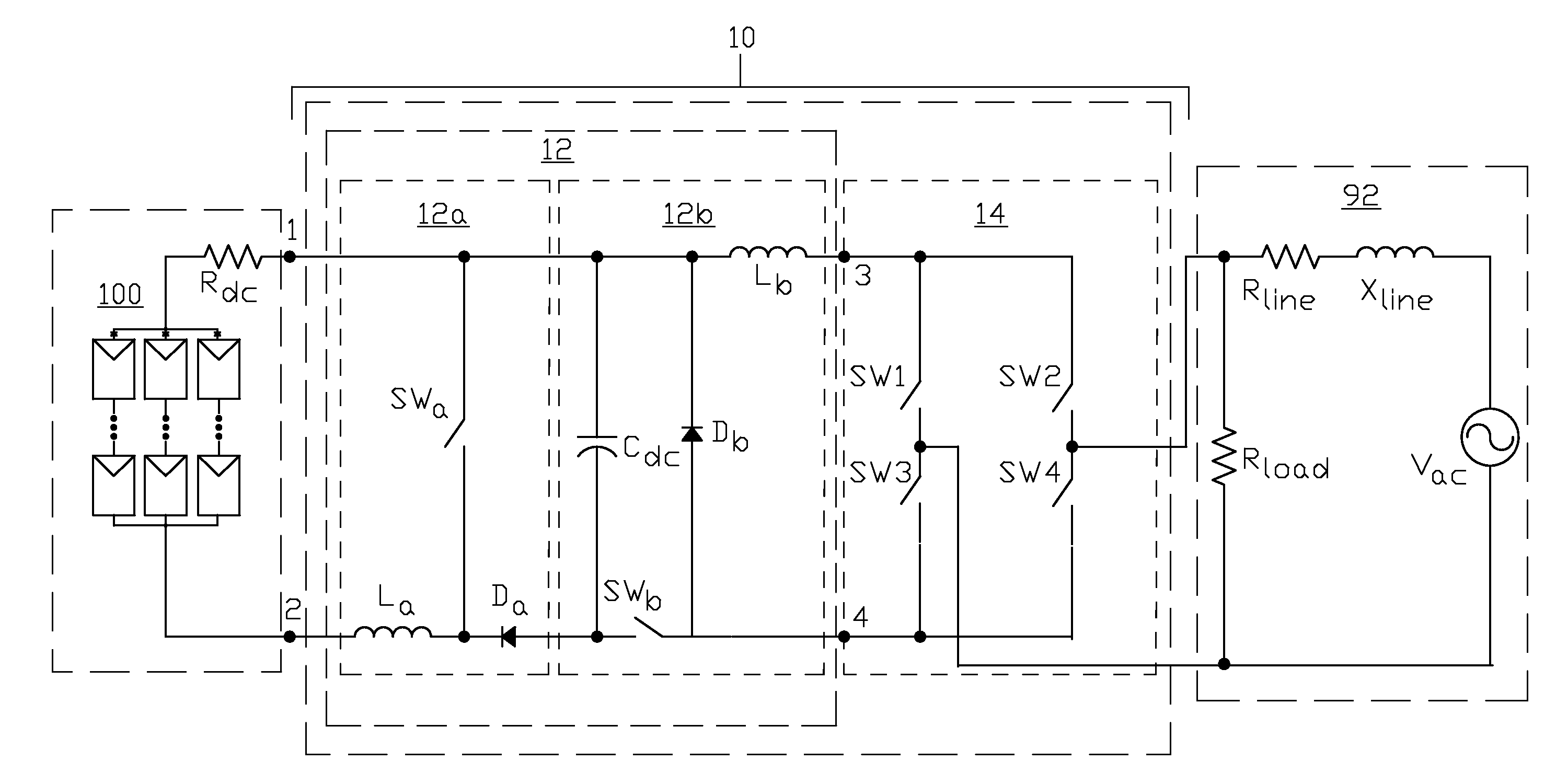
[0083]FIG. 9 illustrates one example of a multiphase grid synchronized regulated current source inverter system of the present invention wherein RCSI 11 inverter section 15 outputs three phase power that undergoes a wye-wye transformation in transformer 70 before being injected into the grid. Regulator section 12 of the RCSI comprises step-up dc current regulator subsection 12a and step-down dc current regulator subsection 12b, which is supplied current from the plurality of dc sources 100 and outputs regulated dc current to the input (points 3 and 4) of three phase inverter 15. The ac outputs (labeled A, B and C in FIG. 9) of this inverter are connected to the wye-configured secondary windings 70b of transformer 70. The wye-configured primary windings 70a of transformer 70 are connected to three phase power grid 92. Grid 92 is schematically represented by lumped line impedances Zline and grid power sources Vac. Current supplied to the grid feeds loads 93, which are con...

example no.2

Example No. 2

[0092]FIG. 13 illustrates another example of a multiphase grid synchronized regulated current source inverter system of the present invention wherein a six phase RCSI system has its output connected to transformer 72 that has branched wye-configured secondary windings. The six phase RCSI system comprises two, three phase regulated current source inverters 11 and 11′, each of which is connected to the six phase secondary windings of transformer 72. First three phase RCSI 11 comprises dc current regulator section 12 and three phase inverter section 15, with plurality of dc sources 100 providing input dc power to RCSI 11. AC outputs A, B and C of inverter 15 are connected to terminals A, B, and C of the secondary windings of transformer 72 as shown in FIG. 13. Similarly second three phase RCSI 11′ comprises dc current regulator section 12′ and three phase inverter section 15′, with plurality of dc sources 100′ providing input dc power to the RCSI 11′. AC outputs R, S and T...

example no.3

Example No. 3

[0103]FIG. 17 illustrates another example of a multiphase grid synchronized regulated current source inverter system of the present invention wherein a nine phase RCSI system has its output connected to transformer 74 that has branched wye-configured secondary windings. The nine phase RCSI system can be used to provide greater output power with a lower THD value than that achieved with the six phase RCSI system described above. The nine phase RCSI system comprises three, three phase RCSI 11, 11′ and 11″, each of which has its output connected to the nine phase secondary windings of transformer 74. First three phase RCSI 11 comprises dc current regulator section 12 and three phase inverter section 15, with plurality of dc sources 100 providing input dc power to RCSI 11. AC outputs A, B and C of inverter 15 are connected to terminals A, B, and C of the secondary windings of transformer 74 as shown in FIG. 17. Similarly second three phase RCSI 11′ comprises dc current regu...


PUM


Abstract

Power from the dc outputs of wind-generated power collection nodes is converted to ac power of suitable quality for injection into an electric power grid. Conversion is accomplished by current regulation of the dc outputs of the wind-generated power collection nodes to the input of each one of multiple inverters in a system, with each inverter outputting multiple phase currents that are out of phase with the multiple phase currents outputted from all other inverters in the system. The multiple phase currents from all of the inverters in a system are connected to the secondary windings of a phase transformation network that produces a three phase current output having a step-shaped waveform for injection into the electric power grid. Alternatively the dc input to each one of the multiple inverters may be a combination of the dc outputs of wind-generated power collection nodes and the dc outputs of solar photovoltaic power collection nodes.

Description

CROSS REFERENCE TO RELATED APPLICATIONS[0001]This application is a continuation-in-part of U.S. application Ser. No. 12 / 325,187 filed Nov. 29, 2008, which is a continuation-in-part of U.S. application Ser. No. 12 / 032,910 filed Feb. 18, 2008, which claims the benefit of U.S. Provisional Application No. 60 / 991,544, filed Nov. 30, 2007, all of which applications are incorporated herein by reference in their entireties.FIELD OF THE INVENTION[0002]The present invention relates to apparatus for, and method of, converting direct current (dc) power from a plurality of typically unstable sources to alternating current (ac) power that is of suitable quality for injection into an electric power grid where the plurality of unstable dc sources are the dc outputs from a plurality of wind turbine driven generator assemblies, or the dc outputs from a plurality of wind turbine driven generator assemblies in combination with the dc outputs from a plurality of photovoltaic power sources.BACKGROUND OF ...

Claims


Application Information

Patent Timeline
Patent Type & Authority Applications(United States)
IPC IPC(8): H02M7/42
CPCH02M7/49Y02E10/56H02M7/497H02M7/493H02M1/0043
Inventor FISHMAN, OLEG S.
Owner ALENCON ACQUISITION
Learn More