Light emitting diode lamp with high heat-dissipation capacity

a technology of light-emitting diodes and heat-dissipation capacity, which is applied in the direction of semiconductor devices for light sources, fixed installations, lighting and heating apparatus, etc., can solve the problems of reduced working efficiency, led damage, and relatively increased working waste heat of led, so as to achieve high heat-dissipation capacity and reduce heat resistance between structure layers.

Inactive Publication Date: 2009-12-10
CHEN HON WEN
View PDF4 Cites 50 Cited by
  • Summary
  • Abstract
  • Description
  • Claims
  • Application Information

AI Technical Summary

Benefits of technology

[0013]The main object of the light emitting diode lamp with high heat-dissipation capacity of the present invention is to provide a lamp in which the lamp body itself is a heat dissipation structure, a metal circuit being directly created on the lamp body so that no additional circuit board is needed. Furthermore, heat resistance between structure layers can be lowered so as to achieve the effectiveness of exhausting the waste heat promptly and concretely from the heat source.

Problems solved by technology

However, the working waste heat of LED is relatively increased with respect to the raising of power.
The temperature increase of the high power LED, reduction on working efficiency and even the damage of LED will be happened if the exhausted waste heat amount is unable to be raised.
When reviewing the present method of heat dissipation for LED lamp, for example the working waste heat of LED contacts with the heat sink through the circuit board and heat sink paste, there are three major defects of heat resistance in the present method of heat dissipation for LED lamp listed as follow.1. A layer of polymer with high heat-resistance for insulation package exists between the heat sink and the LED components such that the heat generated by the LED is unable to be transferred to the heat sink promptly due to the low thermal conduction efficiency of the polymer layer.
Thus, the temperature increase of the LED, reduction on working efficiency and even the damage of LED will be caused to happen.2. LED is mounted on the polymer circuit board with high heat-resistance insulation.
As stated above, the heat generated by the LED is unable to be transferred to the heat sink promptly due to the low conduction efficiency of the polymer layer with high heat-resistance.
Thus, the temperature increase of the LED, reduction on working efficiency and even the damage of LED will be caused to happen.3. Heat sink paste is used between the layers of the structure.
Since the thermal conductivity of the heat sink paste is only 1˜5w / k·m, the heat generated by the LED is unable to be transferred to the heat sink promptly.
Furthermore, bubbles is likely to be produced between the layers of structure and the heat sink paste due to anthropogenic factor during distribution of the heat sink paste, or various heat-resistance situations occur in view of structural defect.
Therefore, huge heat unsteadiness will be occurred on the components.
However, this measure of increasing the efficiency in the heat sink terminal fails to contribute efficiently and reasonably to the improvement or solution with respect to the heat transfer efficiency between the heat source (i.e., the LED) and the heat dissipating terminal (i.e., the heat sink).
However, this technology only improves the heat dissipation structure in the interior of the LED, thus does not provide any efficient solution with respect to the heat jamming in the insulation package layer with high heat-resistance outside the LED.
Secondly, in Japanese Patent No.
This technology improves heat dissipation problem of package layer on the upper portion of electronic components, but fails to solve defect problem of interface between the insulated circuit board with high heat-resistance and the heat sink paste.
In addition, since this technology uses the constitution of small granular diamond mixing with epoxy resin, quartz granule or alumina granule as heat-dissipating insulation package layer for electronic components, the tensile stress feature of which is unable to meet the requirement of suppressing the damage caused by expansion and contraction caused by long-term temperature variation.
Therefore, this technology did not propose a total solution for heat transfer including the items of lowering heat-resistance channels, reducing the complexity of heat conduction structure and the number of interface, ensuring the interface bubbles of the heat sink paste.

Method used


Image

  • Light emitting diode lamp with high heat-dissipation capacity
  • Light emitting diode lamp with high heat-dissipation capacity
  • Light emitting diode lamp with high heat-dissipation capacity

Examples


Embodiment Construction

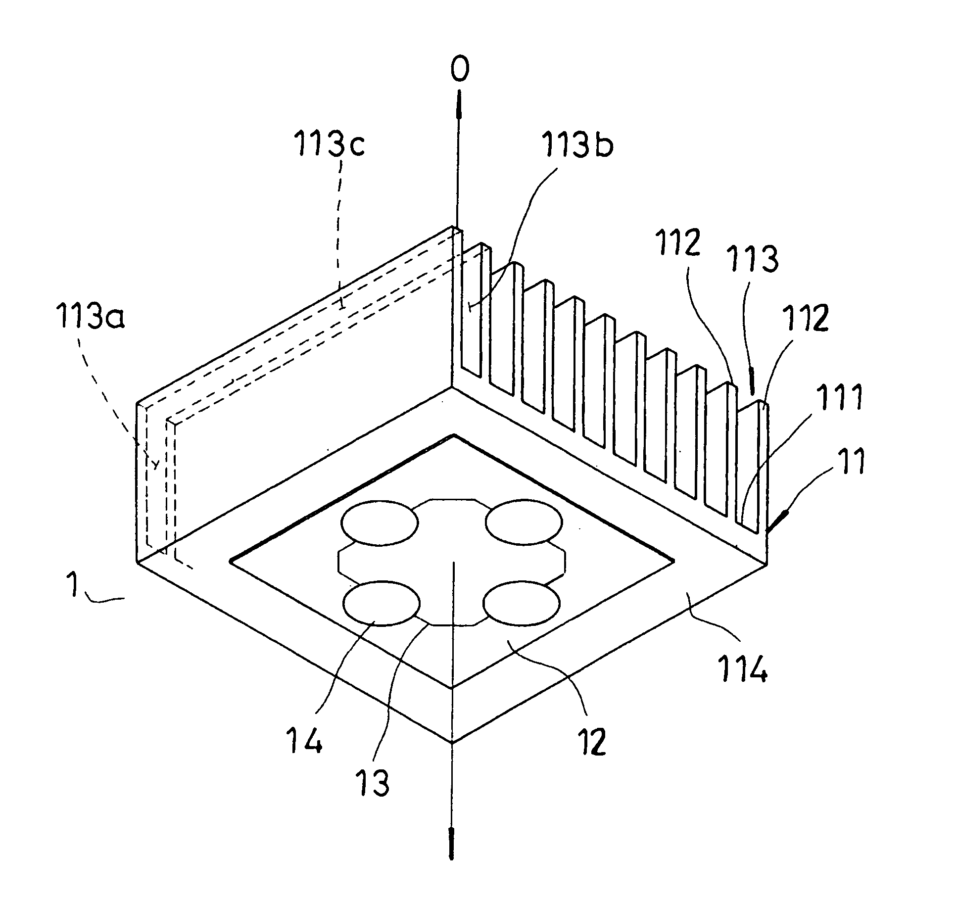
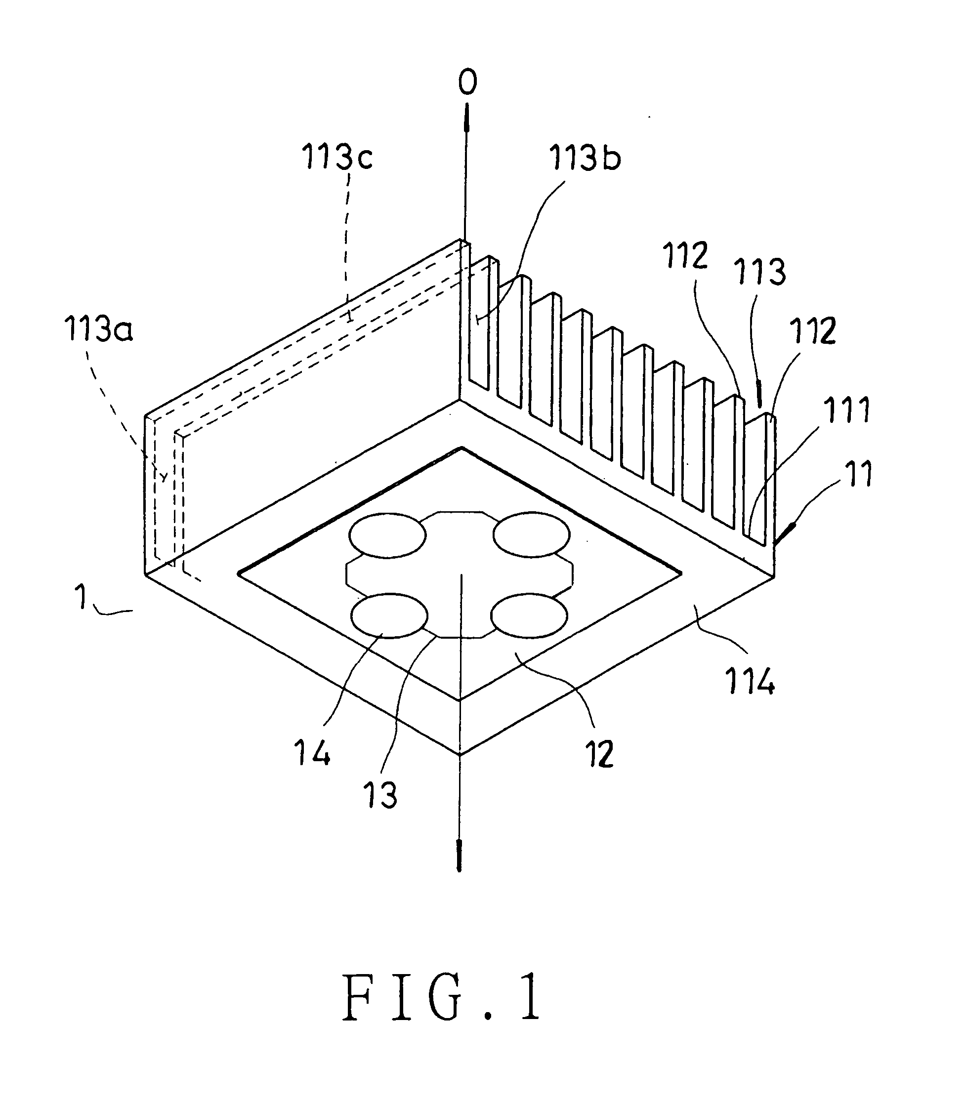
[0057]Referring to FIG. 1 and 2, the first embodiment of the light emitting diode lamp with high heat-dissipation capacity of the present invention are shown.

[0058]In this embodiment, the light emitting diode lamp (1) with high heat-dissipation capacity comprises a plate type heat sink unit (11). A plurality of fins (112) are provided on the heat emitting end (111) to extend along the axial direction (0) of the heat sink unit (11). An air-flow channel (113) is defined between two fins (112), which has two openings (113a), (113b) opposite to each other and a third opening (113c) communicating with both openings (113a), (113b). An electrical insulation layer (12) with high heat conductivity is formed on the heat absorption end (114) of the heat sink unit (11) by a lamination method selected from vapor deposition, sputtering, stamping, injection, screen printing, sintering or spin-coating. The material of the electrical insulation layer (12) with high heat conductivity is a constitutio...


PUM


Abstract

This invention relates to a light emitting diode lamp with high heat-dissipation capacity wherein the lamp has at -least one heat-dissipating unit, a plurality of air-flow channels being provided within each heat sink unit, an electrical insulation layer with high heat-conductivity being provided on the surface of the light emitting diode mounted with heat-dissipating unit, a metal circuit being formed on the electrical insulation layer with high heat-conductivity according to demand, at least one light emitting diode being packaged on the metal circuit such that provision of circuit board or coating of heat sink paste become unnecessary for the lamp.

Description

BACKGROUND OF THE INVENTION[0001]1. Field of the Invention[0002]This invention relates to a light emitting diode lamp with high heat-dissipation capacity, particularly to a lamp without the additional need of a circuit board, and the lamp itself has heat sink unit so as to obtain performance with good heat dissipation efficiency.[0003]2. Brief Description of the Prior Art[0004]Accompanying with perpetual increase of the power of light emitting diode (LED), the percentage of using LED as lamp for illumination is gradually boosted. However, the working waste heat of LED is relatively increased with respect to the raising of power. The temperature increase of the high power LED, reduction on working efficiency and even the damage of LED will be happened if the exhausted waste heat amount is unable to be raised. When reviewing the present method of heat dissipation for LED lamp, for example the working waste heat of LED contacts with the heat sink through the circuit board and heat sink...

Claims


Application Information

Patent Timeline
Patent Type & Authority Applications(United States)
IPC IPC(8): F21V29/00
CPCF21K9/00F21V29/83F21W2131/103F21Y2101/02F28D15/0266F28F1/14F28F3/02F28F13/185H05K1/053H05K2201/0179H05K2201/10106F21V29/006F21V29/763F21V29/773F21S8/086F21Y2115/10F21V29/51
Inventor CHEN, H.W.
Owner CHEN HON WEN
Why Eureka
Try Eureka