Power source apparatus and control method thereof

a technology of power source and control method, which is applied in the direction of electric variable regulation, process and machine control, instruments, etc., can solve the problems of increasing the size, cost, and loss of switching elements of the apparatus, and the inability to provide a plurality of switching elements with predetermined phase differences, so as to increase the parts, size and cost of the apparatus.

Inactive Publication Date: 2009-12-10
SANKEN ELECTRIC CO LTD
View PDF4 Cites 10 Cited by
  • Summary
  • Abstract
  • Description
  • Claims
  • Application Information

AI Technical Summary

Benefits of technology

[0013]The power factor correction circuit disclosed in the Japanese Unexamined Patent Application Publication No. 2006-136046 uses a sawtooth wave generated by a sawtooth wave generator arranged in the controller as a reference to carry out a separately excited switching operation. This is advantageous in providing two step-up choppers with a phase difference of a half

Problems solved by technology

This related art, however, conducts no zero-current or zero-voltage switching, and therefore, causes a switching loss and noise.
In addition, the apparatus adopting the separately excited switching operation needs a device for generating a reference clock, such as the sawtooth wave generator, and therefore, increases the parts, size, and cost of the apparatu

Method used


Image

  • Power source apparatus and control method thereof
  • Power source apparatus and control method thereof
  • Power source apparatus and control method thereof

Examples


embodiment 1

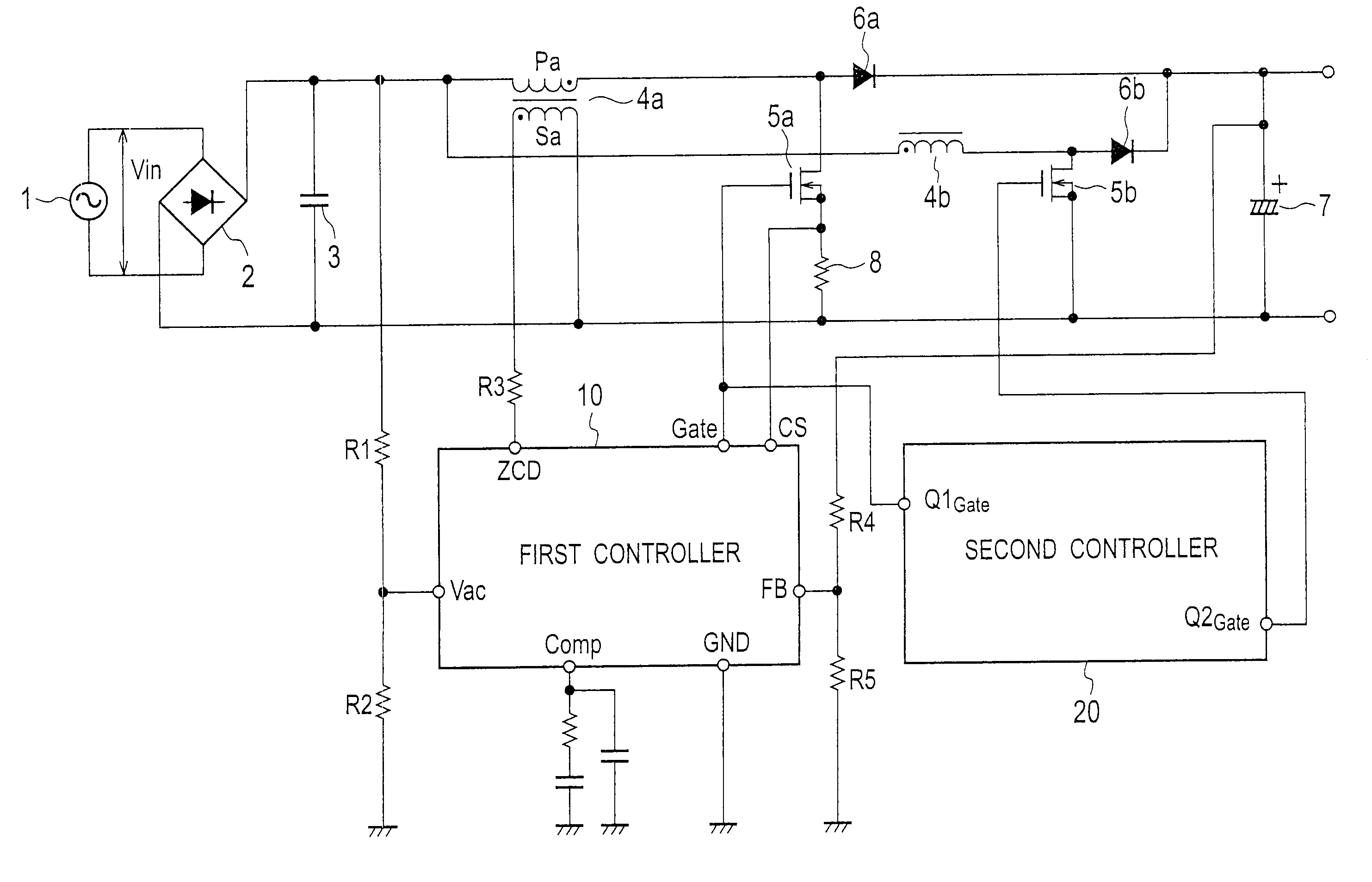
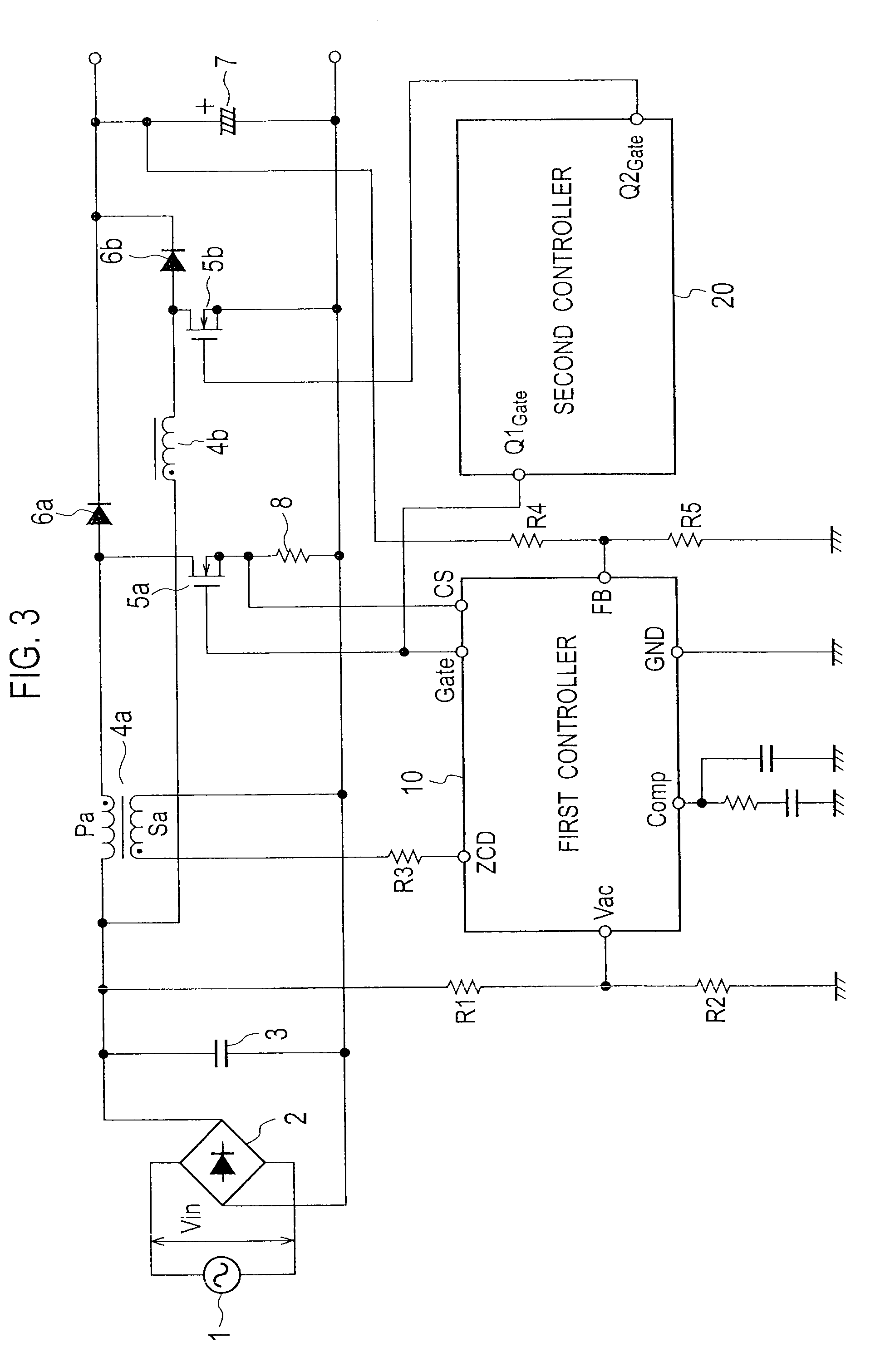
[0032]FIG. 3 is a circuit diagram illustrating a power source apparatus according to Embodiment 1 of the present invention. In FIG. 3 and other drawings illustrating the embodiments of the present invention, the same or equivalent elements as those illustrated in FIG. 1 are represented with the same reference marks as those used in FIG. 1, to omit repeated explanations. The power source apparatus of FIG. 3 according to Embodiment 1 differs from the power source apparatus of FIG. 1 according to the related art in that Embodiment 1 additionally has a power factor correction circuit including a second inductance 4b, a second switching element 5b, and a second diode 6b and a second controller 20 for generating a second control signal used to control the second switching element 5b.

[0033]In the power source apparatus of the present embodiment, an AC power source 1, a bridge rectifier 2, and a capacitor 3 is expressed in terms of the DC voltage generator stipulated in the claims and gene...

embodiment 2

[0085]FIG. 7 is a circuit diagram illustrating the details of a second controller 20 in a power source apparatus according to Embodiment 2 of the present invention. The second controller 20 has a phase synchronizer 21, an ON time generator 22b, and a control signal generator 23b. The phase synchronizer 21 is the same as that of Embodiment 1, and therefore, will not be explained again.

[0086]The ON time generator 22b has frequency dividers 35 and 36, switches 37 and 40, an oscillator 44, and counters 45 and 46. The frequency divider 35 is the same as that of Embodiment 1. The frequency divider 36 divides the frequency of an inverted signal φ2 provided by an inverter 34 in the phase synchronizer 21 by n and generates a frequency divided signal φ4, which is supplied to a terminal CNT of the switch 40 and a terminal CNT of a switch 47 in the control signal generator 23b.

[0087]Each of the counters 45 and 46 achieves an adding mode if a voltage at a terminal UP is high. In the adding mode...

embodiment 3

[0120]A power source apparatus according to Embodiment 3 will be explained. The power source apparatus of Embodiment 3 differs from that of Embodiment 1 in that it has three power factor correction circuits including switching elements and that it employs a second controller 20 whose configuration is different from that of Embodiment 1. Although a general view illustrating the power source apparatus of Embodiment 3 is not provided, it includes, in addition to the power source apparatus of one of Embodiments 1 and 2, a power factor correction circuit including a third switching element and connected in parallel with the other power factor correction circuits. Namely, the power source apparatus of Embodiment 3 employs three power factor correction circuits that operate at phase differences of 120 degrees.

[0121]FIG. 9 is a circuit diagram illustrating the details of the second controller 20 in the power source apparatus according to the present embodiment. The second controller 20 rece...


PUM


Abstract

A power source apparatus includes a DC voltage generator (1, 2, 3) to generate a DC voltage, a plurality of voltage converters connected in parallel with one another and each having a switching element (5a/5b) to convert the DC voltage generated by the DC voltage generator into a predetermined DC voltage, a first controller 10 to generate a first control signal for controlling ON/OFF of one of the switching elements contained in the plurality of voltage converters, and a second controller 20 to control, according to the first control signal, the switching elements other than the switching element controlled by the first controller.

Description

BACKGROUND OF THE INVENTION[0001]1. Field of the Invention[0002]The present invention relates to a power source apparatus for generating a predetermined DC voltage through switching operation and a control method thereof.[0003]2. Description of the Related Art[0004]Switching power source apparatuses of office automation tools and consumer appliances mostly include power factor correction converters. The switching power source apparatuses are required to improve efficiency in view of environmental considerations and energy saving. An example of a power factor correction converter used for the switching power source apparatus is disclosed in Japanese Unexamined Patent Application Publication No. H05-111246. This related art employs, as a power source circuit to convert an AC input into a DC output, a capacitor-input-type converter incorporating a power factor correction circuit known as a step-up chopper.[0005]FIG. 1 is a circuit diagram illustrating the power source apparatus (power ...

Claims


Application Information

Patent Timeline
IPC IPC(8): H02M3/22
CPCH02M1/4225Y02B70/126H02M3/1584Y02B70/10
Inventor USUI, HIROSHI
Owner SANKEN ELECTRIC CO LTD
Why Eureka
Try Eureka