

Field emission cathode and x-ray tube embodying same
- Summary
- Abstract
- Description
- Claims
- Application Information
AI Technical Summary
Benefits of technology
Problems solved by technology
Method used
Image

Examples
Embodiment Construction
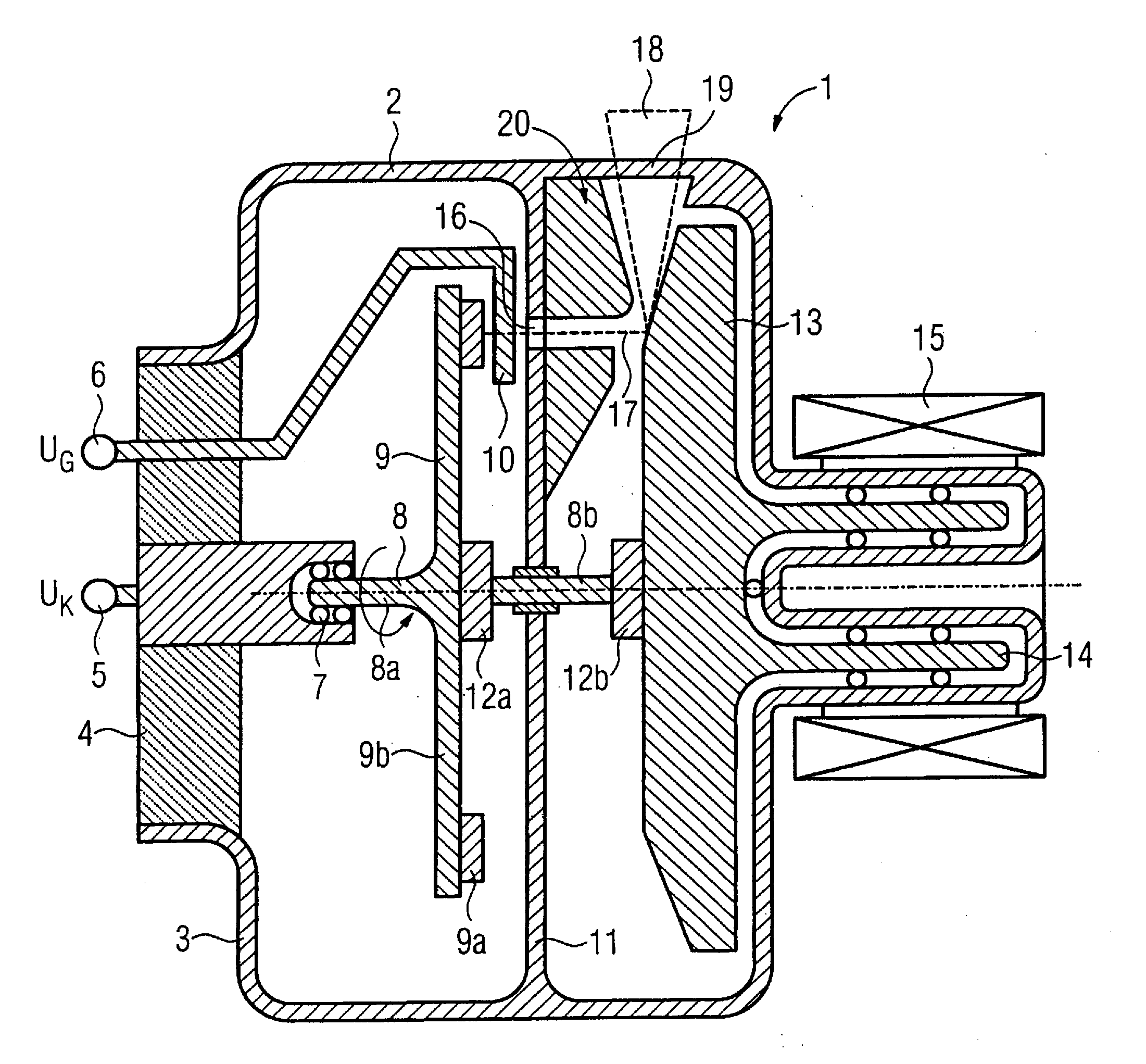
[0042]An x-ray tube 1 that is executed as a rotary anode x-ray tube is shown in FIG. 1.
[0043]The x-ray tube 1 has a stationary vacuum housing 2 with a high-voltage side 3 that possesses an insulating body 4 made of ceramic.
[0044]The x-ray tube 1 is mounted in a known manner in a radiator housing (now shown). A coolant liquid is located between the vacuum housing 2 and the radiator housing.
[0045]A high voltage connection (terminal) 5 and a high voltage connection 6 are arranged in the insulating body 4. The high voltage connection 5 is at a cathode potential UK, for example −120 kV, and is connected to an electrically conductive bearing 7 in which a shaft 8 is mounted such that it can rotate. A field emitter 9 is arranged on the shaft 8 such that it is rotationally fixed.
[0046]The high voltage connection 6 is connected to a stationary extraction grid 10 at a grid potential UG that increases the negative cathode potential UK by an extraction potential UE of, for example, +2 kV. In the...
PUM
 Abstract
Description
Claims
Application Information