Electrical resistance heating element for a heating device for heating a flowing gaseous medium

a heating element and electric resistance technology, which is applied in the direction of electric heating, fluid heaters, air heaters, etc., can solve the problems of insufficient flow of air and unusable heating elements, and achieve the effect of improving electrical resistance heating elements and reducing the danger of overheating

Inactive Publication Date: 2009-12-10
LEISTER TECHNOLOGIES
View PDF22 Cites 22 Cited by
  • Summary
  • Abstract
  • Description
  • Claims
  • Application Information

AI Technical Summary

Benefits of technology

[0011]The invention addresses the problem of proposing an improved electrical resistance heating element for a heating device for a flowing gaseous medium, wherein the danger of overheating is reduced even without special protective measures.

Problems solved by technology

If the resistance heating elements used there are operated without a sufficient flow of air for a certain amount of time, the heating wire will usually burn through, thereby rendering the heating element unusable.
An insufficient flow of air may be caused, for example, by a failure of the blower or a restriction of the air inlet or air outlet cross-section of the hot air device.

Method used


Image

  • Electrical resistance heating element for a heating device for heating a flowing gaseous medium
  • Electrical resistance heating element for a heating device for heating a flowing gaseous medium
  • Electrical resistance heating element for a heating device for heating a flowing gaseous medium

Examples


first embodiment

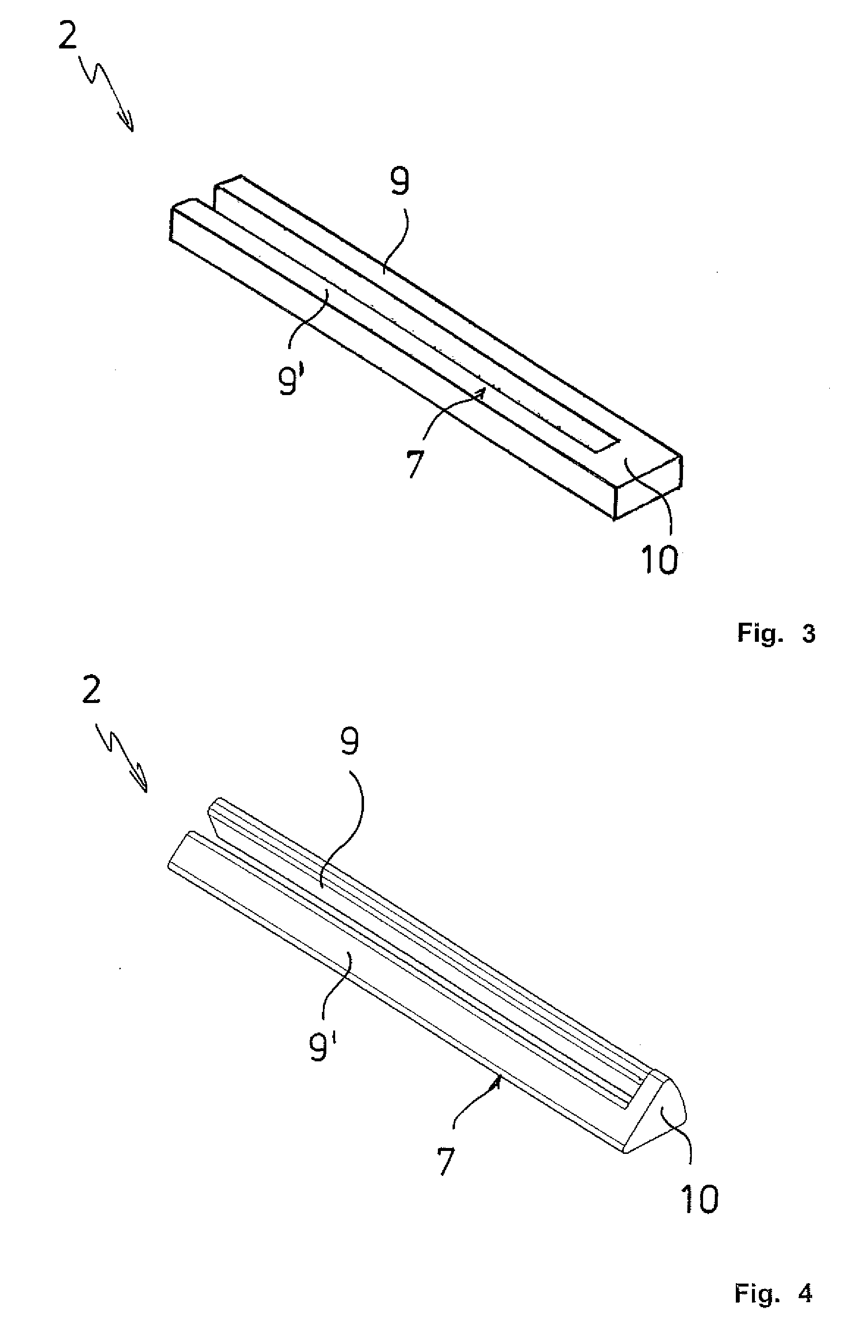
[0040]FIG. 3 shows the U-shaped heating resistor 2 made of an electrically conductive ceramic material. The limbs 9, 9′ and the base 10 have a square cross-section and are located on one plane. The surface 7 is flat.

[0041]FIG. 4 shows a second variant of the heating resistor 2 shown in FIG. 3 where the limb 9 has a rectangular cross-section and the limb 9′ and the base 10 have a triangular cross-section, all together forming a cylinder segment that corresponds to one eighth of a straight circular cylinder. The surfaces 7 of the limbs 9, 9′ are flat and inclined towards each other.

third embodiment

[0042]FIG. 5 shows the U-shaped heating resistor 2. The limbs 9, 9′ and the base 10 have an essentially triangular cross-section. They are designed so that together they form a cylinder segment that corresponds to one quarter of a circular cylinder. The surface 7 of the limbs 9, 9′ is structured. It has indentations 21 and raised areas 22 in order to enlarge the surface 7 for its contact with the flow of air. In addition, the structured surface 7 has the advantageous effect of creating turbulence of the flow of air, and thereby ensuring uniform heating thereof.

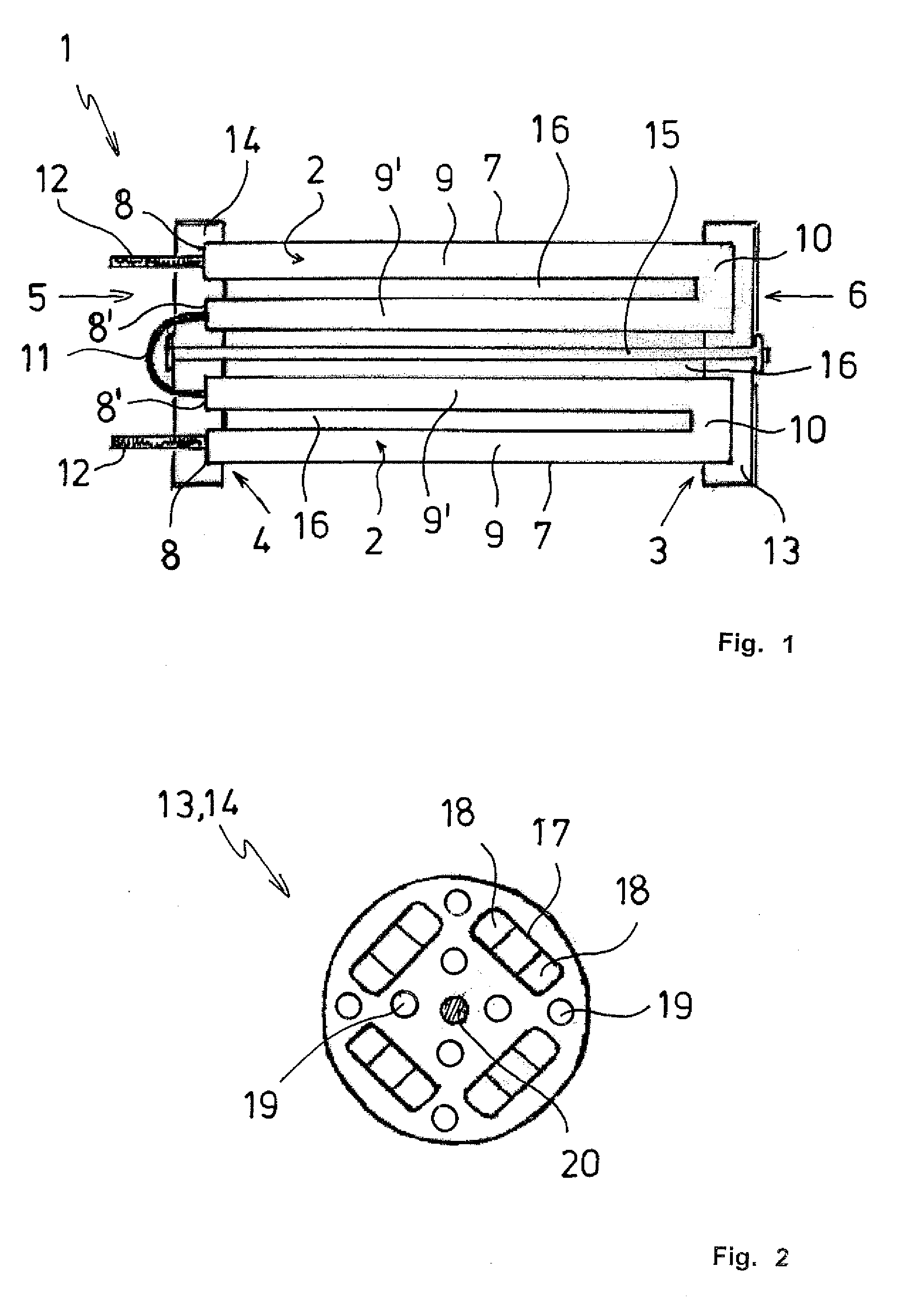
[0043]FIG. 6 shows the carrier plates 13, 14 that match the heating resistor 2 shown in FIG. 5. The carrier plates 13, 14 have a ring-shaped, essentially rectangular recess 17 and are suitable for a positive connection to the heating resistors 2. For this purpose, the heating resistors 2 are positioned in the corners 23 of the recess 17. In addition, the carrier plates 13, 14 have passages 19 for the flow of air, and the reces...


PUM


Abstract

An electrical resistance heating element for a heating device, with at least one flow canal through which the gaseous medium is able to flow from a canal inlet side to a canal outlet side of the resistance heating element, and with at least one heating resistor that extends essentially in the direction of the flow canal, with the medium flowing past the heating resistor and being heated in the process. The heating resistor is rod-shaped and produced from an electrically conductive ceramic material. The electrical resistance heating element is intended for installation in a heating tube into which air, for example, is blown at one end. The heated flow of air exits from the other end of the heating tube.

Description

CROSS-REFERENCE TO RELATED APPLICATION [0001]The present application claims priority under 35 USC §119 to European Patent Application No. 08 010 426.8, filed on Jun. 9, 2008, the entire disclosure of which is incorporated herein by reference.TECHNICAL FIELD OF THE INVENTION [0002]The invention concerns an electrical resistance heating element for a heating device for heating a gaseous medium, with at least one heating resistor that extends essentially in the longitudinal direction of the electrical resistance heating element, with the medium flowing past the heating resistor and being heated in the process. The resistance heating element has at least one flow canal that extends along the heating resistor and through which the gaseous medium is able to flow from a canal inlet side to a canal outlet side of the resistance heating element, with the heating resistor consisting of an electrically conductive ceramic material for conducting the current. The invention also relates to a heat...

Claims


Application Information

Patent Timeline
Patent Type & Authority Applications(United States)
IPC IPC(8): F24H3/04
CPCF24H3/0405F24H3/0423H05B3/141H05B2203/02H05B3/42H05B2203/018H05B3/16
Inventor GUBLER, ULRICHZURBUCHEN, RETOPRESTAT, MICHELVOGT, ULRICH
Owner LEISTER TECHNOLOGIES
Why Eureka
Try Eureka