Asynchronous counter based timing error detection

a counter and detection technology, applied in the field of timing error detection, can solve the problem of analog approach that is inferior in deep submicron technology

Active Publication Date: 2009-12-10
REALTEK SEMICON CORP
View PDF3 Cites 21 Cited by
  • Summary
  • Abstract
  • Description
  • Claims
  • Application Information

AI Technical Summary

Problems solved by technology

The nature of this approach is analog that

Method used


Image

  • Asynchronous counter based timing error detection
  • Asynchronous counter based timing error detection
  • Asynchronous counter based timing error detection

Examples


Embodiment Construction

[0019]In the present disclosure, numerous specific details are provided, such as examples of electrical circuits, components, and methods, to provide a thorough understanding of embodiments of the invention. Persons of ordinary skill in the art will recognize, however, that the invention can be practiced without one or more of the specific details. In other instances, well-known details are not shown or described to avoid obscuring aspects of the invention.

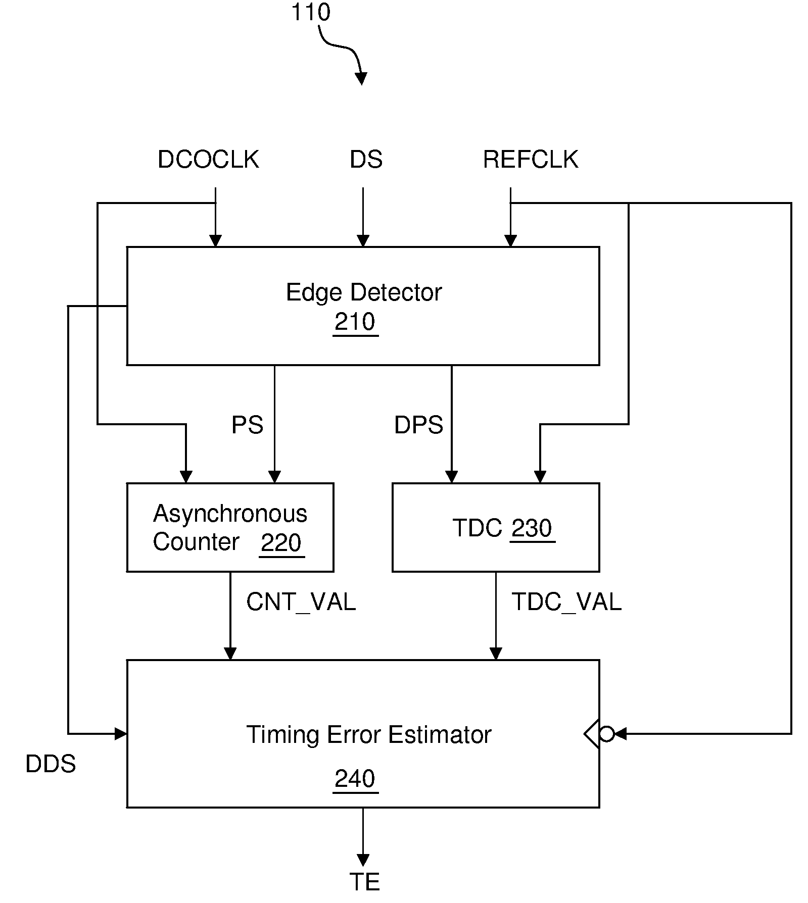
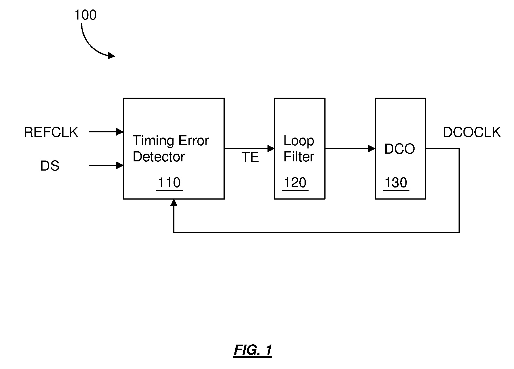
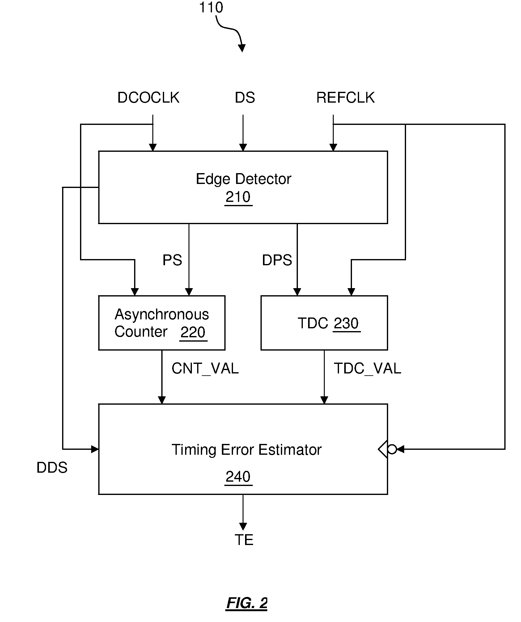
[0020]FIG. 1 shows an all-digital phase-locked loop in accordance with the present invention. The all-digital phase-locked loop 100 comprises a timing error detector 110, a loop filter 120, and a digitally controlled oscillator (DCO) 130. In one embodiment, the timing error detector 110 is configured to receive a first clock DCOCLK from the digitally controlled oscillator 130, a second clock REFCLK, and a dither signal DS and to generate a timing error TE between the first clock and a fictitiously desired clock. The fictitiously d...


PUM


Abstract

A method for estimating a timing difference between a first clock signal and a second clock signal is disclosed. The estimating method comprising: generating an edge signal by detecting an edge of the second clock signal by sampling the second clock signal using the first clock signal; generating a delayed edge signal by a further sampling of the second clock signal using the first clock signal; generating a first intermediate code by counting a number of clock edges of the first clock signal within a duration defined by the edge signal using an asynchronous counter; generating a second intermediate code to represent a timing difference between the second clock signal and the delayed edge signal using a time-to-digital converter; and generating an output code using a weighted sum of the first intermediate code and the second intermediate code.

Description

RELATED APPLICATION[0001]This application claims the benefit of U.S. Provisional Application No. 61 / 059,238, filed on Jun. 5, 2008, having the title “TIMING DETECTION USING AN ASYNCHRONOUS COUNTER IN A FRACTIONAL-N FREQUENCY SYNTHESIZER.”, the contents of which are incorporated herein by reference.BACKGROUND OF THE INVENTION[0002]1. Field of the Invention[0003]The present invention relates generally to a timing error detector. In particular, it relates to the design of an asynchronous counter based timing error detector.[0004]2. Description of the Background Art[0005]The phase-locked loop is a key building block as it can generate a well-defined frequency. The prior art uses a phase-frequency detector and a charge pump to extract the timing relationship between a reference clock and an oscillator clock. The nature of this approach is analog that is inferior in deep submicron technology. An asynchronous counter based timing error detector is presented in this work that utilizes an al...

Claims


Application Information

Patent Timeline
IPC IPC(8): G06F1/06
CPCG04F10/005H03K5/1534H03K21/023H03L2207/50H03L7/091H03L7/10H03K23/58
Inventor HSIEH, HONG-YEAN
Owner REALTEK SEMICON CORP
Why Eureka
Try Eureka