Insulated concrete form panel reinforcement

a technology of insulated concrete and form panels, which is applied in the direction of shaping building parts, building components, walls, etc., can solve the problems of inability to meet the requirements of a high-vulcanity location, the support of t-walls or columns is less well known in the past, and the location of high vulnerability of traditional spacers used in other locations in the icf system is not particularly suitabl

Inactive Publication Date: 2009-12-17
PHIL INSUL CORP
View PDF38 Cites 40 Cited by
  • Summary
  • Abstract
  • Description
  • Claims
  • Application Information

AI Technical Summary

Benefits of technology

[0019]It is an object of the present invention to obviate or mitigate at least one disadvantage of previous ICF panels, pre-assembled blocks and systems.
[0022]Surprisingly, the combination of a panel reinforcement with an integrated spacer retention element was found to add additional support in locations which are highly vulnerable to blow-out (such as at T-wall intersections). Using the reinforcement of the present invention on a main panel directly opposite the intersecting panel opposing panels in the ICF system can be connected by spacers in the usual manner while at the same time stiffening the main panel. The reinforcement is sufficiently sized so that it can protect the entire length of the panel, from top to bottom, when connected to the panel, and not merely at point locations in the panel. Further, the reinforcement can be used with opposing panels which are offset by differing heights or widths, or which face each other at different angles.
[0023]Advantageously, the reinforcement of the present invention can be readily retrofitted to any ICF panel, including those panels which are flipable, reversible and bi-directional. With panels having a dovetailed arrangement, or other interlocking elements, on their surface, a reinforcement can be manufactured to slide into the complementary interlocking elements on the panel, greatly facilitating the addition of reinforcements at the job site. However, any means for connecting the reinforcement to the panel can be used, such as with adhesives or the like. Alternatively, the reinforcements can be integrally manufactured in pre-fabricated ICF panels or a pre-assembled block.
[0024]As a further advantage, a panel having a reinforcement connected thereto in accordance with the present invention can be used anywhere in an ICF system, and in particular at locations having a high vulnerability for blow-out, without requiring additional supports or reinforcements as commonly used in previous ICF systems known in the art.

Problems solved by technology

However, a previously-prepared assembly is not usually practical because of increased labour, variations in the wall heights and sizes and / or angles at corners throughout the ICF system.
The support of T-walls or column is less well known in the prior art, and especially not in ICF systems.
However, traditional spacers which are used in other locations in the ICF system may not be particularly suitable at locations of high vulnerability, such as at the T-wall intersection.
Additional spacers alone may not be sufficient to prevent blow-out at T-wall intersections.
The absence of a wall directly opposing the main wall at the point of intersection is one reason why adequately supporting the T-wall has been challenging, since it is more difficult to add spacers to maintain the fixed spacing between the main panel and the opposing panels of the intersecting T-wall.
Because of the increased vulnerability of the main wall panel to increased stress, the panel itself must be reinforced.
The plates are only secured to the top of the panels, leaving the bulk of the panel vulnerable to stress.
This can compromise the integrity of the form, leading to an infiltration of unwanted moisture and dust and potential form failure.
An inward-projecting (i.e., toward the intersection) block is situated on the main wall to help reinforce the panel at the T-wall intersection; however, no additional supporting means are used specifically at the T-wall intersection.
However, that system requires braces on both the interior surface of the panels as well as the exterior surface, and only connects to the top of the panel.
There have existed several problems with existing methods of protecting vulnerable locations in an ICF system from blow-out.
While the installation of additional supports at these vulnerable locations has sought to reduce the incidence of blow-out by supplementing already-existing braces and / or spacers which keep opposing panels in place, merely adding additional supports may not necessarily prevent blow-outs if the supports are not properly positioned at the vulnerable location.
In addition, prior T-wall assemblies have only protected opposing panels, without protecting or supporting the highly-vulnerable location on the main panel directly opposite the end of the intersecting panel(s).
Further, if the brackets are not properly secured to the panel, either due to poorly-fitting brackets / spacers or because of a lack of sufficient time at the job site to properly retrofit the panels, the spacers may become disengaged from supporting brackets, or disassemble from the panel altogether.
Ultimately, the spacers may only serve to hold the panels at a fixed distance from each other, rather than adding any additional stabilization.
This lack of stabilization increases the risk of blow-out which can result in unnecessary and costly delays to the project.
In addition, the spacers themselves may not be suitable or structurally adequate to cope with increased pressure at the vulnerable locations.
Selecting the right spacer at the right location can be a challenge and inconvenient.
If an improper spacer is chosen, there may still be an increased risk of blow-out regardless of any added support.
Attempts to reinforce or stabilize the T-wall or column by buttressing the exterior side of the main panel can be challenging.
One problem with these exterior supports is that their installation at the job site can add a considerable amount of time to perform a particular task, as it requires the builder to interrupt or delay the pouring of concrete within the form until the extra buttresses are added.
The absence of sufficient space to anchor the buttress to the ground or a sufficiently sturdy location renders their placement more difficult, particularly in multi-level construction.

Method used


Image

  • Insulated concrete form panel reinforcement
  • Insulated concrete form panel reinforcement
  • Insulated concrete form panel reinforcement

Examples


Embodiment Construction

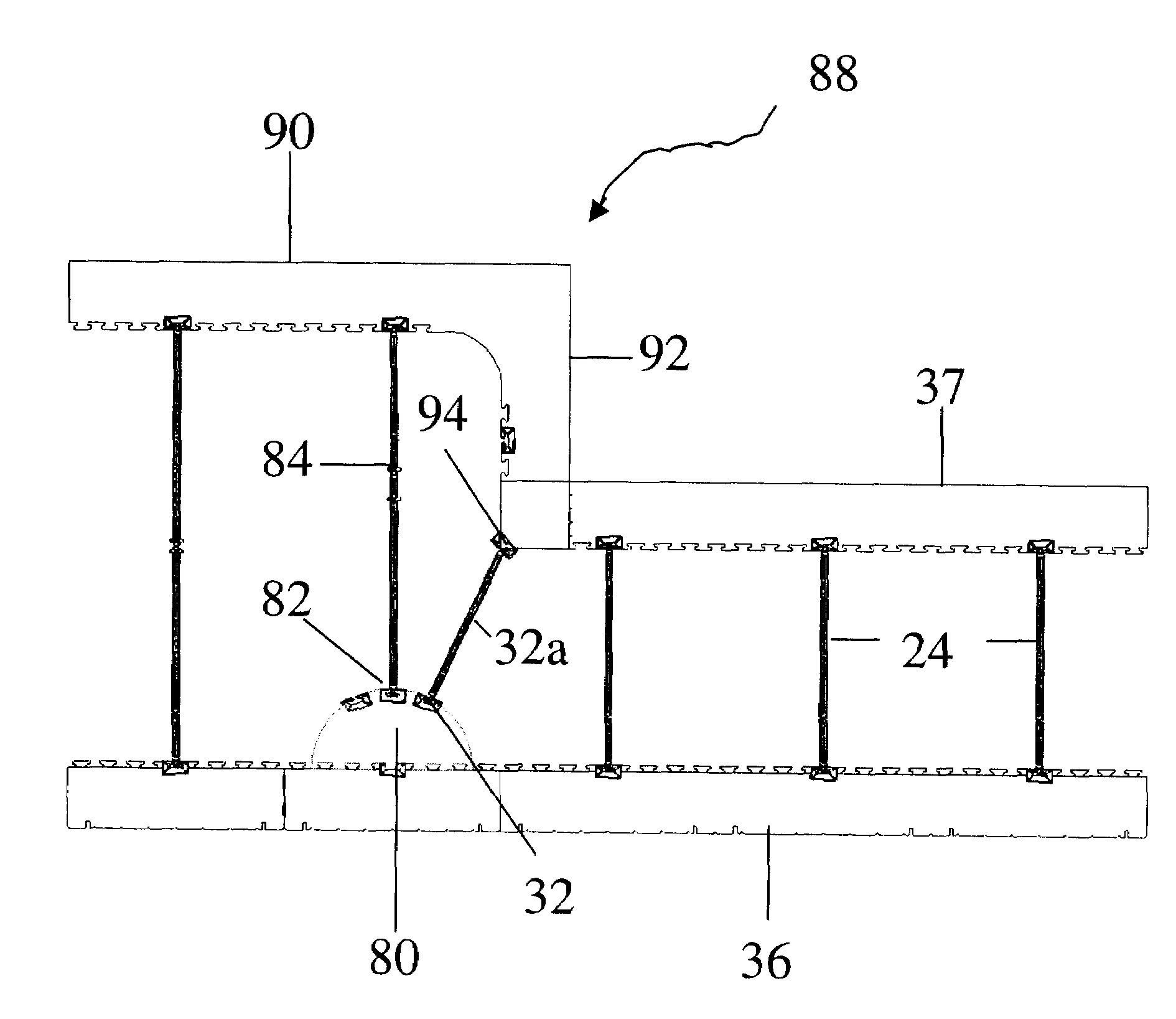
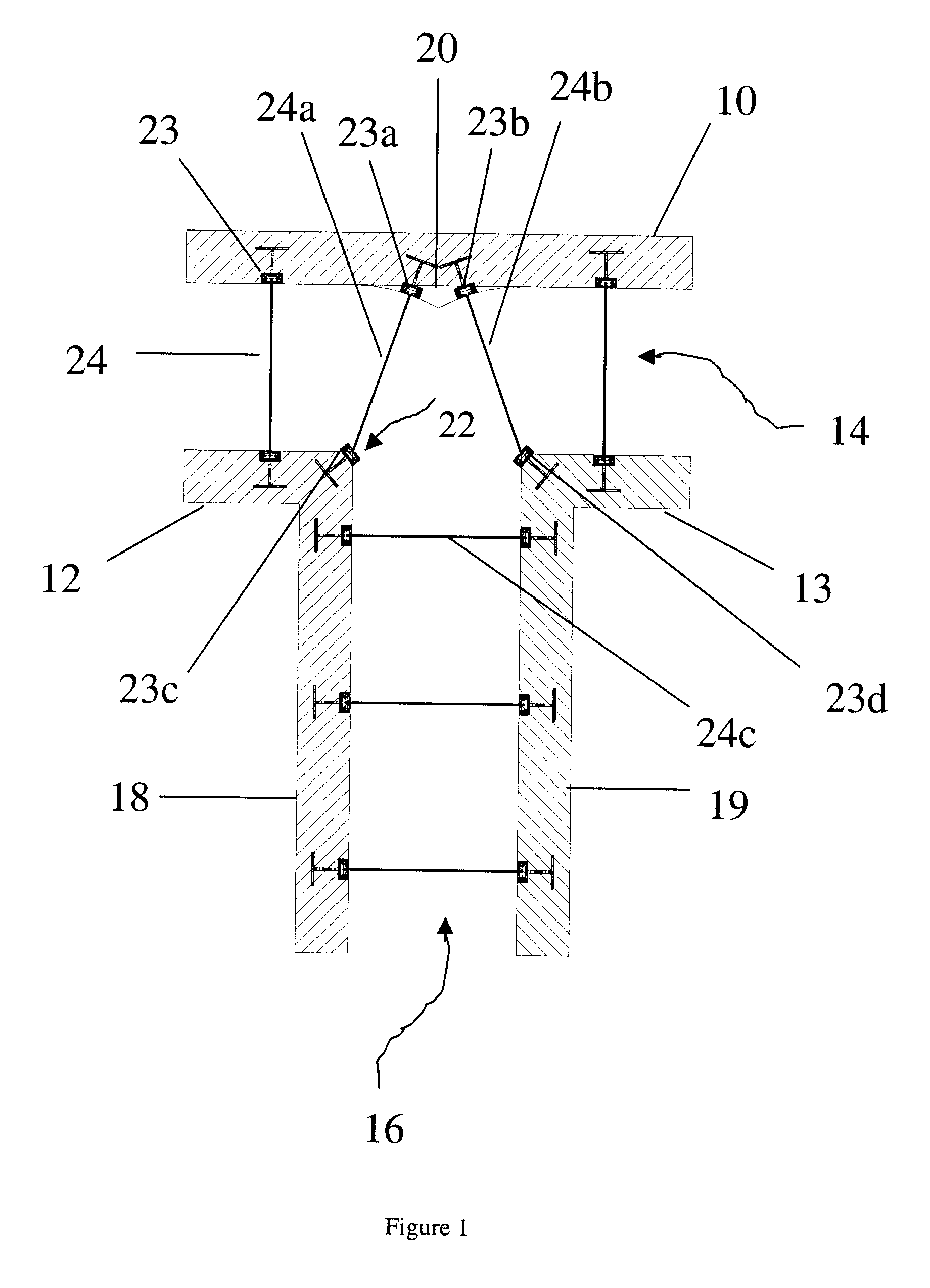
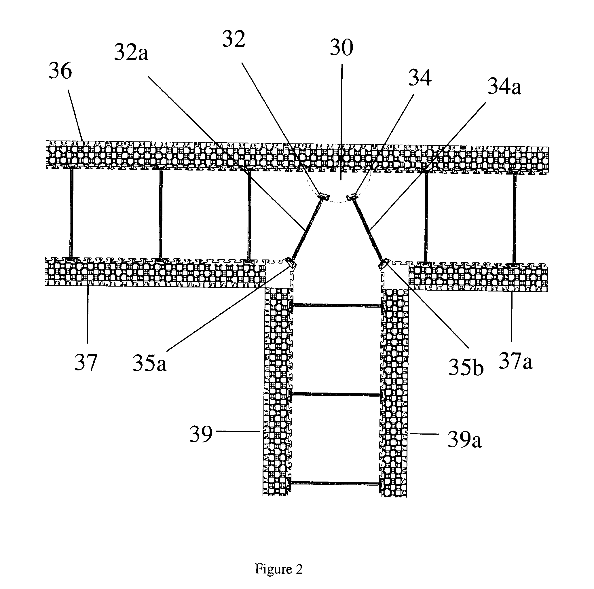
[0039]Generally, the present invention provides an ICF system having a reinforcement at a T-wall intersection. More particularly, the present invention provides an insulated concrete form comprising a main panel, a first opposing panel opposite the main panel, a spacer having first and second ends for maintaining a fixed spacing between the main panel and the first opposing panel, a reinforcement on the main panel for stiffening the main panel, a spacer retention element integrated in the reinforcement for securing the first end of the spacer to the main panel, and a first opposing spacer retention element in the first opposing panel for securing the second end of the spacer to the first opposing panel.

[0040]A panel having a reinforcement connected thereto in an ICF according to the present invention is referred to herein as a reinforced panel. The reinforced panel can be used at any location along an ICF system. The reinforced panel is particularly suitable at locations vulnerable ...


PUM

PropertyMeasurementUnit
angleaaaaaaaaaa
angleaaaaaaaaaa
angleaaaaaaaaaa

Abstract

An insulated concrete form (ICF) panel reinforcement is disclosed. The ICF comprises a main panel, a reinforcement on the main panel for stiffening the main panel, a spacer retention element integrated in the reinforcement for securing a spacer to the panel, and a first opposing panel opposite the main panel and having a first opposing spacer retention element integrated therein for securing the spacer to the first opposing panel. The ICF panel reinforcement is particularly useful at high stress locations in ICF systems, such as at T-wall intersections.

Description

FIELD OF THE INVENTION[0001]The present invention relates generally to insulated concrete wall forms. More particularly, the present invention relates to a reinforcement for a panel or block in an insulated concrete form system.BACKGROUND OF THE INVENTION[0002]Insulated concrete forms (ICFs) are used in the construction of insulated concrete walls in a variety of building applications. In a system of ICFs, a series of opposing panels or pre-assembled block are separated, preferably by a distance equal to the thickness of the desired concrete wall, thus providing a channel, wall or column cavity into which concrete is poured. A typical ICF can comprise a pre-assembled block and / or one or more outside or main panels, and one or more inside or opposing panels across the wall cavity. Each panel usually has an exterior surface and an interior surface. In contrast to the exterior surfaces which generally do not oppose or connect with any other panels in the ICF, the interior surfaces of t...

Claims


Application Information

Patent Timeline
Patent Type & Authority Applications(United States)
IPC IPC(8): E04B2/44E04G11/06E04G17/06E04B1/21E04G11/50
CPCE04B2/8635E04C3/34E04B2002/867
Inventor PHILIPPE, MICHEL JOSEPH RENE
Owner PHIL INSUL CORP
Why Eureka
Try Eureka