Charging method, battery pack and charger for battery pack

a charging method and battery pack technology, applied in the direction of electric vehicles, transportation and packaging, electric generators, etc., can solve the problems of voltage difference between the voltage across the terminal and the cell voltage that can be consumed, and achieve the effect of preventing an application of overvoltage, preventing an overcharge of the respective cell, and increasing the charge amoun

a charging method and battery pack technology, applied in the direction of electric vehicles, transportation and packaging, electric generators, etc., can solve the problems of voltage difference between the voltage across the terminal and the cell voltage that can be consumed, and achieve the effect of preventing an application of overvoltage, preventing an overcharge of the respective cell, and increasing the charge amoun

US20090309547A1Inactive Publication Date: 2009-12-17PANASONIC CORP

Image

  • Charging method, battery pack and charger for battery pack
  • Charging method, battery pack and charger for battery pack
  • Charging method, battery pack and charger for battery pack

Examples


first embodiment

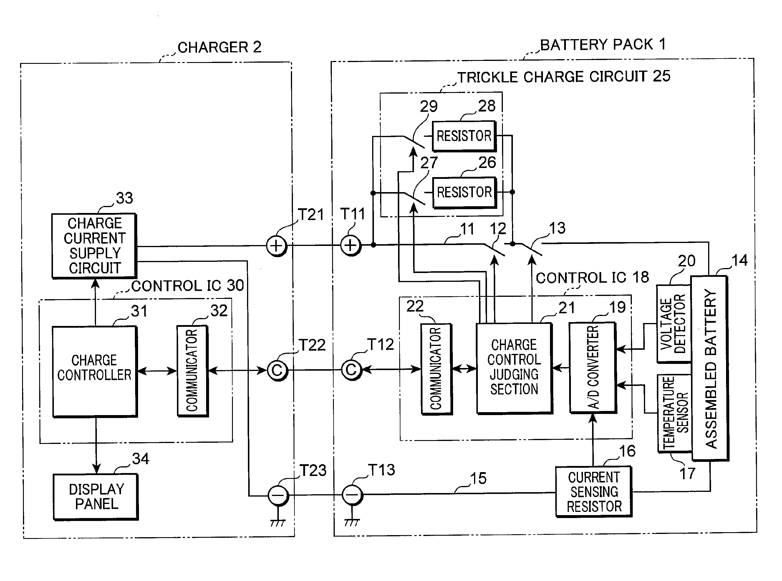
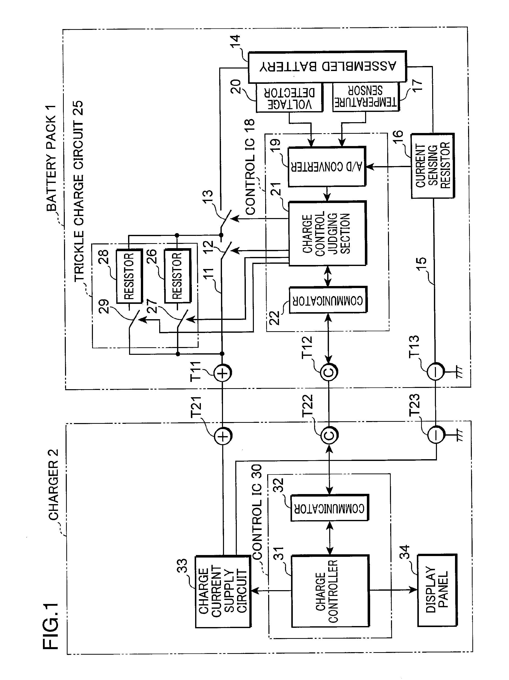
[0020]FIG. 1 is a block diagram showing the electrical structure of a charging system employing a charging method according to a first embodiment of the present invention. As shown in FIG. 1, the charging system includes a battery pack 1 and a charger 2 for charging the battery pack 1. The charging system of the present invention is not limited to the foregoing structure, and may further include a load equipment (not shown), to which power is supplied from the battery pack 1. In the case of the charging system of FIG. 1, the battery pack 1 is charged by the charger 2; however, in the case of the above example of the charging system provided with the load equipment, the battery pack 1 may be mounted on the load equipment to be charged via the load equipment. The battery pack 1 and the charger 2 are interconnected by high voltage direct current terminals T11, T21 for power supply, terminals T12, T22 for communication signals, and GND terminals T13, T23 for power supply and communicati...

second embodiment

[0048]FIG. 6 is a block diagram showing the electrical structure of a charging system employing a charging method according to a second embodiment of the present invention. This charging system is similar to the one shown in FIG. 1 and corresponding parts are identified by the same reference numerals and not described. An essential feature of the charging system in accordance with the present embodiment lies in that only the conventional series circuit of the current limiting resistor 26 and FET 27 is provided in a trickle charge circuit 25c of a battery pack 1a and, instead, a charge current supply circuit 33a of a charger 2a can supply a current I12 in the middle-speed current charging area.

[0049]Thus, a charge control judging section 21a of a control IC 18a performs the trickle charging in a similar manner to the conventional method by switching ON the FETs 13, 27 and using the current limiting resistor 26 in the initial stage of the charging process as described above. The charg...


PUM


Abstract

A charging method includes a constant-current charging step wherein a constant charge current is supplied to a secondary battery to be charged to a predetermined end voltage; and a constant-voltage charging step wherein the predetermined end voltage is maintained by reducing the charge current after said secondary battery is charged to the end voltage, wherein: said constant-current charging step includes the charging step to be carried out with the end voltage set to OCV which is a voltage when no current is flowing, and with a voltage of a charge terminal of said battery pack set to an overvoltage above said OCV, and said constant-voltage charging step includes the step of reducing the voltage across the charge terminals to the after the voltage across the charge terminals is increased to the overvoltage or after the charge current of the charge terminal is reduced to or below a predetermined current level.

Description

TECHNICAL FIELD[0001]The present invention relates to a charging method, a battery pack and a charger for the battery pack, and more particularly relates to a technique for reducing a charging time.BACKGROUND ART[0002]FIG. 7 is a graph showing a typical conventional method for controlling a charge voltage and a charge current, which realizes a shorter charging time. FIG. 7 shows the case of a lithium ion battery, wherein α1 indicates changes in charge voltage of a secondary battery and α2 indicates changes in charge current to be supplied to the secondary battery.[0003]Firstly, changes in charge voltage are explained. A trickle charging area, wherein a small constant current I1, e.g. a charge current of 50 mA is supplied, starts from the beginning of the charging and ends when a cell voltage of one cell, or cell voltages of all the plurality of cells have reached the same end voltage Vm for the trickle charging e.g. 2.5 V.[0004]When the cell voltage reaches the end voltage Vm, a tra...

Claims


Application Information

Patent Timeline
17 Dec 2009
Publication
US20090309547A1
IPC
H02J7/00; H02J7/04; H02J7/06
CPC
H01M10/441; H02J7/06; H02J7/045; H02J7/0086; Y02E60/10; H02J7/04; H02J7/00714; H02J7/007182
Inventors
NAKATSUJI, TOSHIYUKI