
Mobile actuating device

a technology of actuating device and mobile device, which is applied in the direction of mechanical control device, electrical apparatus casing/cabinet/drawer, instruments, etc., can solve the problems of adversely affecting the electronic unit and its function, and achieve the effect of improving the invention and special touch properties

Active Publication Date: 2009-12-17
HUF HULSBECK & FURST GMBH & CO KG
View PDF5 Cites 1 Cited by
  • Summary
  • Abstract
  • Description
  • Claims
  • Application Information

AI Technical Summary

Benefits of technology

[0004]The invention is based on the task of modifying a mobile actuating device of the above-mentioned type, in which the internal space is reliably protected from environmental effects, the actuating device can be produced cost-effectively, and increased demands relating to appearance and key touch properties are achieved. At the same time, a control capability with respect to method of function of the actuating device is to be made available simply to the user.
[0005]For this purpose, it is proposed according to the invention that the first housing shell has a display for optical depiction of information, especially in conjunction with the method of operation of the electronic unit and / or the state of the locking system, with an opening made in the first housing shell from which a light signal that can be generated within the housing can be emitted, whereby the support element, which is connected in one piece to the operating element, is designed to be transparent and is made of a first material with a limited modulus of elasticity, and the opening is completely filled up by at least part of the support element, so that the light signal can be guided outward through the support element, through the opening and the operating element, which is made of a second material, whereby the second material has a much greater modulus of elasticity than the first material.
[0006]The support element in the present invention lies directly on the side of the first housing shell facing the internal space, whereby it simultaneously assumes several functions. In the first place, the support element seals the internal space reliably, so that moisture, water, dust, etc., cannot reach the internal space, where it can adversely affect the electronic unit and its function. In the second place, the support element serves as a support means for the operating element. It has been found that by using the first material with a low modulus of elasticity, a responsive sense of touch is attainable in the user by operating the operating element, which consists of the second material having a much greater modulus of elasticity than the first material. Since the support element is arranged directly on the operating element, a compact design is simultaneously achieved. It is particularly advantageous that, for optical display of information, the support element acquires a type of guide function, so that the light signal generated within the actuating device is guided outward through the opening of the first housing shell. The display can be designed so that by operation of an operating element, the user can check whether the actuating device, especially the electronic unit, is functioning. When a light signal (for example, colored red) leaves the display, it means for the user that the actuating device is fully functional. The display can also convey optical information concerning the state of locking or unlocking of the locking system. It is conceivable to provide a state message about the locking system by multicolored light signals that leave the display. The displays can assume different geometric shapes. In one possible embodiment, the display can be a point-like surface. As an alternative to this, the display can be designed as a large-surface display accommodated by a corresponding opening of the first housing shell.
[0010]The operating element can advantageously be brought from a rest position to an operating position by applying an external force, whereby the support element is designed so that in the operating position, a restoring force acts starting from the support element, which brings the operating element back to its rest position. It is particularly advantageous that in the operating position of the operating element, a restoring force is formed only from the support element, which brings the operating element with the support element back to the rest position. In one possible embodiment of the actuating device, the support element has a camber directed toward the internal space along the peripheral gap. This camber favors the restoring force of the support element that develops in the operating position of the operating element. The camber also means that lengthening of the control path of the operating element from its rest position into the operating position can be achieved. A light element is appropriately assigned to the opening, whereby the support element is situated between the opening and the light element. The light element can be an LED.
[0012]The support element appropriately has a head area accommodated by the opening. The opening of the first housing shell is advantageously completely filled by the head area of the support element. If light is generated in the actuating device, it passes through the head area and leaves the display outward. Since the head area fully closes the opening, there is no danger that any dirt particles, water, moisture, etc., can reach the internal space of the actuating device through the display.
[0013]A step that improves the invention can prescribe that a protrusion made on the side of the support element facing the internal space is provided that contacts the switch element in the operating position of the operating element. The protrusion acts as a type of lifter that activates the switch element in the operating position of the operating element. Special touch properties for the user can be achieved thereby.

Problems solved by technology

In the first place, the support element seals the internal space reliably, so that moisture, water, dust, etc., cannot reach the internal space, where it can adversely affect the electronic unit and its function.

Method used


Image

  • Mobile actuating device
  • Mobile actuating device
  • Mobile actuating device

Examples


Embodiment Construction

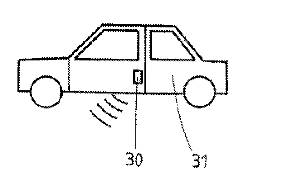
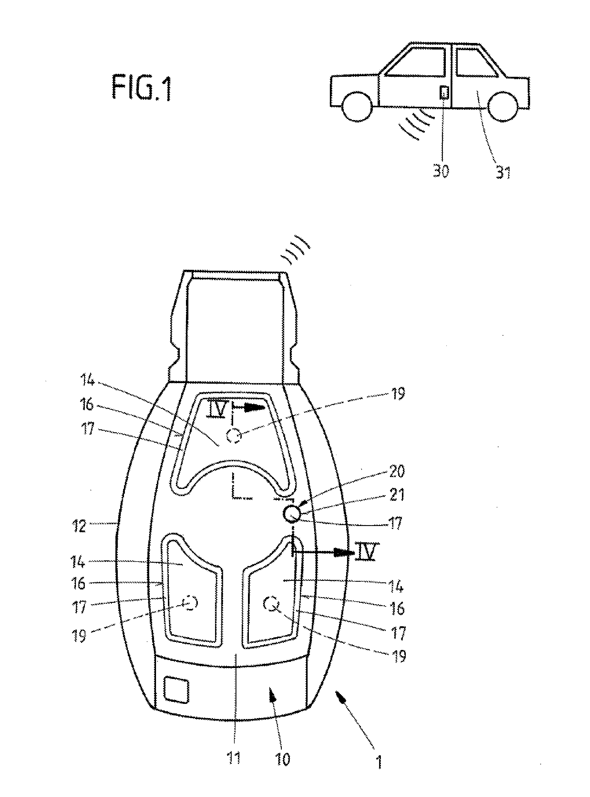
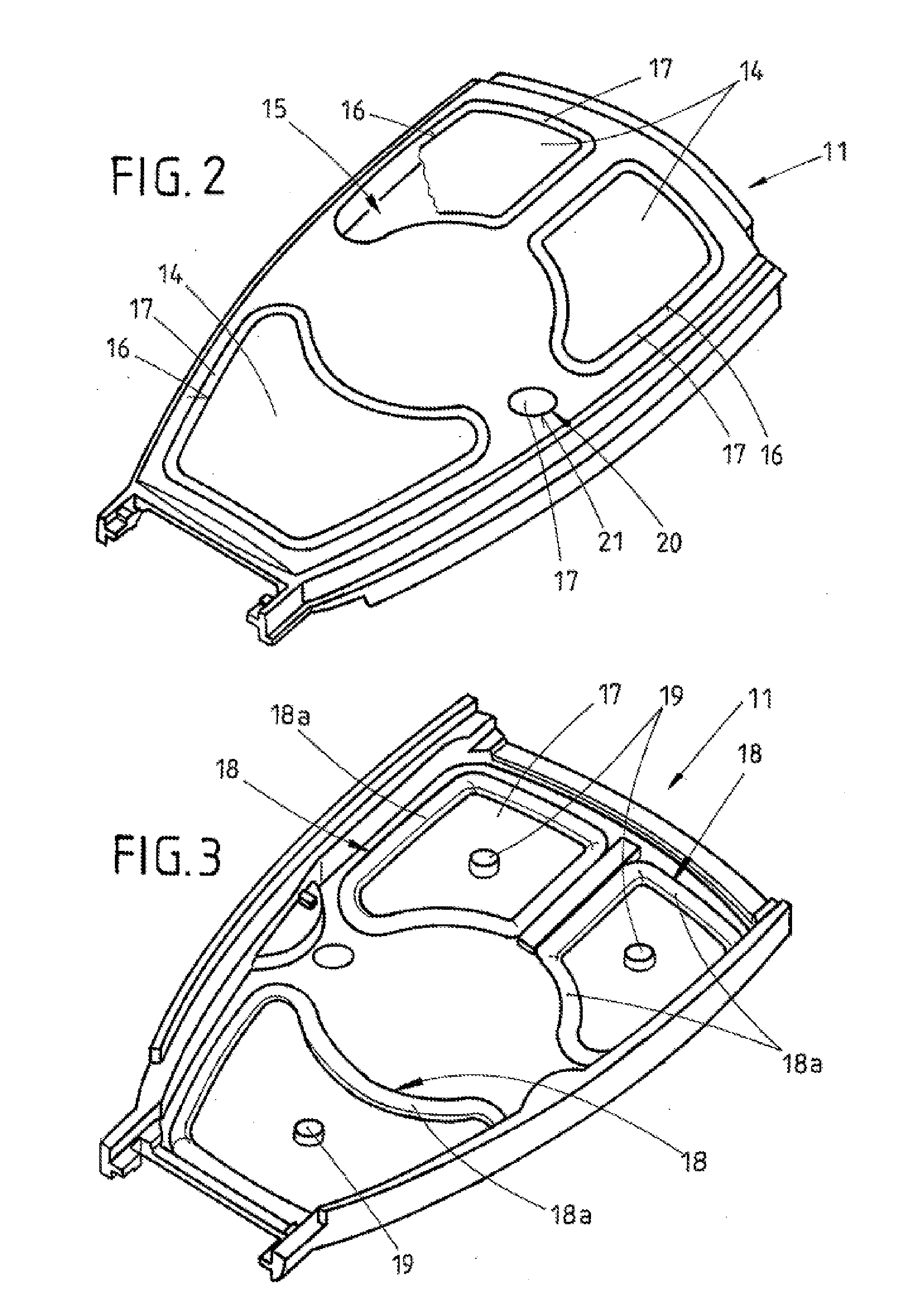
[0020]A mobile actuating device 1 is shown in FIG. 1, which is used as an electronic key for remote control of a locking system 30 of a vehicle 31. The actuating device 1 has a housing 10 having a first 11 and a second housing shell 12. The second housing shell 12 is arranged on the back. The first housing shell 11 in the present embodiment example has three operating elements 14 arranged within a housing opening of the first housing shell 11. The housing opening 15 is shown here in FIG. 2. A peripheral gap 16 is situated between the first housing shell 11 and each operating element 14. The mobile actuating device also has an internal space 13, which is shown as an example in FIG. 4. The internal space 13 is bounded at least partially by the housing shells 11, 12, an electronic unit 40 being arranged within internal space 13 for data communication with the locking system 30. In the present example, the electronic unit 40 has a circuit board 43, onto which a switch element 41 and a l...


PUM


Abstract

The invention relates to a mobile actuating device (1) particularly for the remote control of a locking system (30) of a vehicle (31), comprising a housing (10) having first (11) and second (12) housing shells, an interior chamber (13) which is delimited at least partially by the housing shells (11, 12), an electronic unit (40) for data communication with the locking system (30), the unit being provided at least partially inside the interior chamber (13), at least one actuating member (14) disposed inside a housing opening (15) of the first housing shell (11), a circumferential gap (16) between the actuating member (14) and the first housing shell (11), a carrier element (17) which is provided on the side of the first housing shell (11) facing the interior chamber (13), and a switching element (41) connected to the electronic unit (40) and associated with the actuating member (14). According to the invention, the first housing shell (11) comprises a display (20) for the optical display of information, particularly in connection with the mode of operation of the electronic unit (1) and / or with the state of the locking system (30), having an opening (21) in the first housing shell (11), wherein a light signal (50) generated inside the housing (10) can be emitted from said opening, wherein the carrier element (17), which is attached to the actuating member (14) as one piece, is translucent and made of a first material having a low modulus of elasticity, and wherein the opening (21) is completely filled by at least part of the carrier element (17), whereby the light signal (50) can be conducted via the carrier element (17) through the opening (21) to the outside, and the actuating member (14), which is made out of a second material, has a considerable larger modulus of elasticity than the first material.

Description

FIELD OF THE INVENTION[0001]The invention relates to a mobile actuating device, especially for remote operation of a locking system of a vehicle, with a housing having a first and second housing shell, an internal space, bounded at least partially by the housing shells, an electronic unit arranged at least partially within the internal space for data communication with the locking system, at least one operating element arranged within a housing opening of the first housing shell, a gap running between the operating element and the first housing shell, a support element provided on the side of the first housing shell facing the internal space, and a switch element connected to the electronic unit, which is connected to the operating element.BACKGROUND OF THE INVENTION[0002]Such mobile actuating devices are widely used in order to accommodate the electronics of a remote control on the user side, which can be designed as a transmitter a transmitter with a receiver, or a transponder. Su...

Claims


Application Information

Patent Timeline
IPC IPC(8): H05K7/00B60R25/20B60R25/24
CPCB60R25/2009B60R25/24G07C9/00944G05G1/02H01H9/0235H01H9/161H01H2221/002G07C2009/00984B60R25/10E05B19/04G07C9/00H01H9/02
Inventor JESCHKE, ALEXANDER
Owner HUF HULSBECK & FURST GMBH & CO KG
Features
  • Generate Ideas
  • Intellectual Property
  • Life Sciences
  • Materials
  • Tech Scout
  • Unparalleled Data Quality
  • Higher Quality Content
  • 60% Fewer Hallucinations
Learn More