Boat Stabilizer, Boat Motor and Related Method

a technology for stabilizers and boats, applied in the field of boat stabilizers, can solve the problems of creating unnecessary drag, difficulty in drilling holes in the precise location needed, and permanent modification of the structure of the lower drive uni

Active Publication Date: 2009-12-24
MARINE DYNAMICS
View PDF58 Cites 22 Cited by
  • Summary
  • Abstract
  • Description
  • Claims
  • Application Information

AI Technical Summary

Benefits of technology

[0008]In accordance with the present invention, a boat stabilizer is provided which over

Problems solved by technology

A problem inherent in the after-market boat stabilizers used heretofore is that they are bolted directly on to the anti-cavitation plate of the boat motor.
Many boat owners simply do not want to permanently modify the structure of their lower drive units in this manner.
Furthermore, drilling the holes in the precise location needed can be difficult.
Gaps and open spaces between the boat stabilizer and anti-cavitation plate can hold water which creates unnecessary drag.
In addition, drilling holes in the anti-cavitation plate can void the engine manufacturer's anti-corrosion protection warranty on new engines.
Another problem associated with the boat stabilizers currently available is that the stabilizers do not sufficiently harness the thrust energy generated by rotation of the boat motor propeller.
Unfortunately, a great deal of the thrust energy created by the boat motor is lost.
As a result, some of the water in the thrust cone ultimately is thrown above the surface and into the air,

Method used


Image

  • Boat Stabilizer, Boat Motor and Related Method
  • Boat Stabilizer, Boat Motor and Related Method
  • Boat Stabilizer, Boat Motor and Related Method

Examples


Embodiment Construction

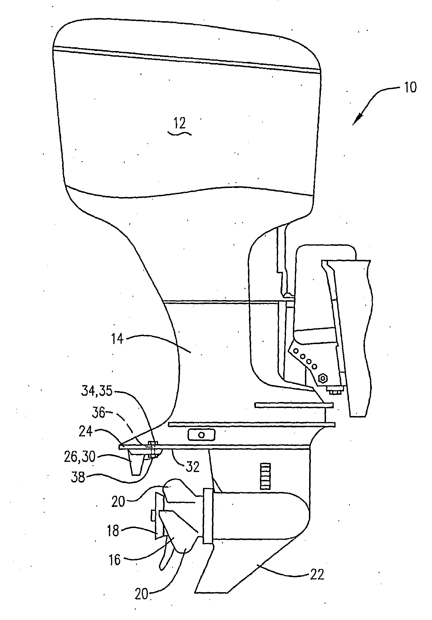
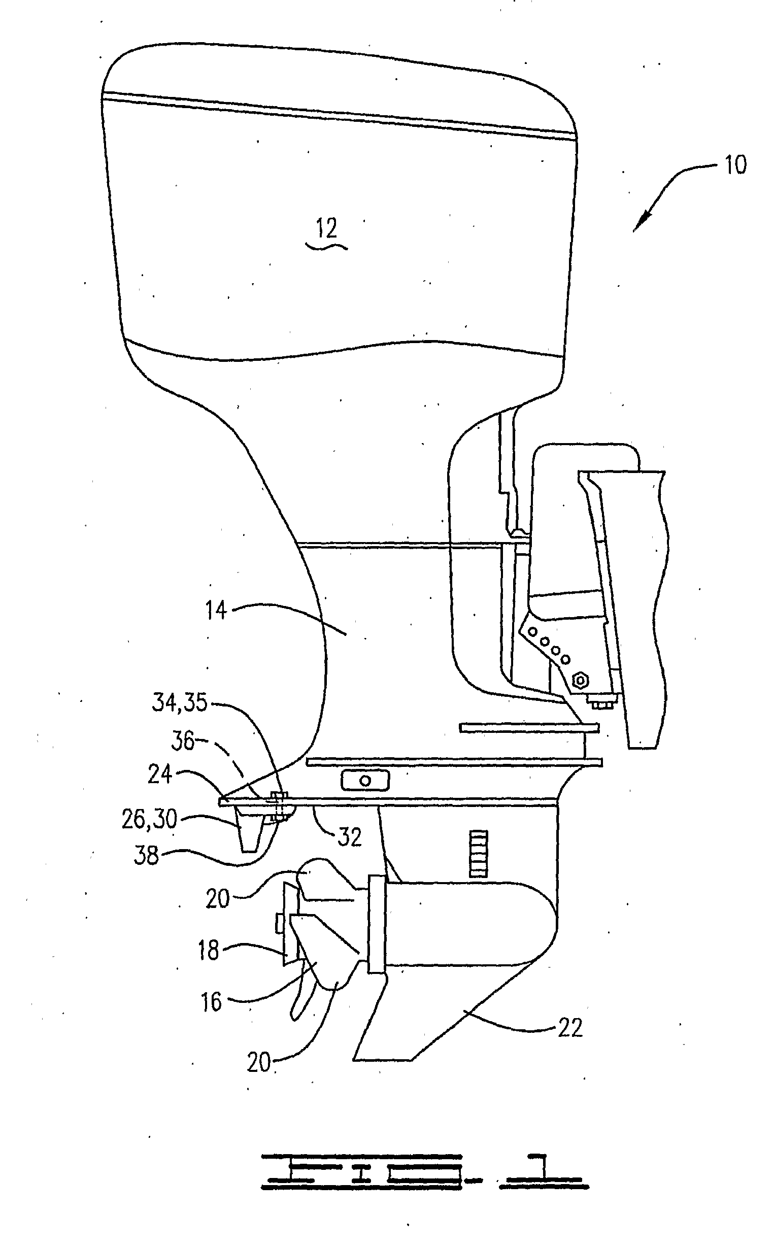
[0043]Referring now to the drawings, and particularly to FIG. 1, a boat motor suitable for use in connection with the present invention is illustrated and generally designated by the numeral 10. The boat motor 10 includes an engine 12 (illustrated with the engine cover or housing attached to the engine) and a lower drive unit 14 attached thereto. Although the boat motor 10 shown in FIG. 1 is an outboard motor, other types of motors including motors having stern drive units can also be used in association with the present invention. For example, with respect to the present invention, the lower drive unit 14 is the same regardless of whether the boat motor 10 is an outboard or a stern drive.

[0044]As shown by FIG. 1, the lower drive unit 14 includes a propeller 16 including a propeller hub 18 and a plurality of blades 20. A skeg 22 is attached to the lower drive unit 14 and extends below the propeller 16. An anti-cavitation plate 24 is also attached to the lower drive unit 14 and is di...


PUM

PropertyMeasurementUnit
Lengthaaaaaaaaaa
Lengthaaaaaaaaaa
Lengthaaaaaaaaaa

Abstract

A boat stabilizer that is attachable to the anti-cavitation plate or other structure of the lower drive unit of a boat motor without permanently modifying the structure of the anti-cavitation plate or other structure is provided. The shape and size of the boat stabilizer causes the stabilizer to effectively harness and control the thrust energy generated by the propeller resulting in improved thrust and fuel efficiency. Due to various features, the drag associated with the boat stabilizer is kept to a minimum. Finally, decals and other decorative elements are integrally embedded into the top surface of the inventive boat stabilizer using in-mold decoration (“IMD”) technology which makes the elements resistant to ultra-violet light, virtually indestructible and highly appealing. A boat motor, a method of attaching a boat stabilizer to a boat motor and a method of molding a boat stabilizer having at least one decorative element integrally embedded in the top surface thereof are also provided.

Description

BACKGROUND OF THE INVENTION[0001]The present invention relates to boat stabilizers that are attachable to the lower drive unit of a boat motor to provide lift to the stern of the boat and otherwise improve the performance of the boat. The invention also relates to boat motors having a boat stabilizer attached thereto, methods of attaching a boat stabilizer to the lower drive unit of a boat motor and methods of manufacturing boat stabilizers.[0002]It is known that the stability, performance, fuel efficiency and safety of certain types of boats (for example, ski boats, bass boats, pontoon boats and the like) can be improved by the addition of an after-market boat stabilizer to the lower drive unit of the boat motor. Such boat stabilizers, often referred to as hydrofoil stabilizers or hydrofoils, are typically designed to fit around the rear of the drive unit over or under the anti-cavitation plate thereof. The boat stabilizers are bolted on to the anti-cavitation plate. Examples are s...

Claims


Application Information

Patent Timeline
IPC IPC(8): B63B1/24B29C35/08B63B1/32B63H1/28B63H1/18B23P11/00
CPCB63H20/34Y10T29/49948Y02T70/542Y02T70/50
Inventor TEMPLEMAN, STEVEN WTEMPLEMAN, JON C.
Owner MARINE DYNAMICS
Why Eureka
Try Eureka