
Fluidic device

a fluid device and magnetic actuator technology, applied in fluid pressure control, laboratory glassware, instruments, etc., can solve the problems of high cost of mechanical arms, inconvenient to carry, and labour-intensive work of conventional biochemical reaction experiments, and achieve the effect of small and portabl

Inactive Publication Date: 2009-12-24
IND TECH RES INST
View PDF5 Cites 4 Cited by
  • Summary
  • Abstract
  • Description
  • Claims
  • Application Information

AI Technical Summary

Benefits of technology

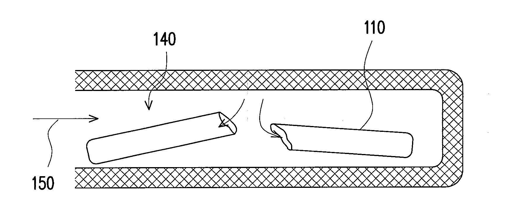
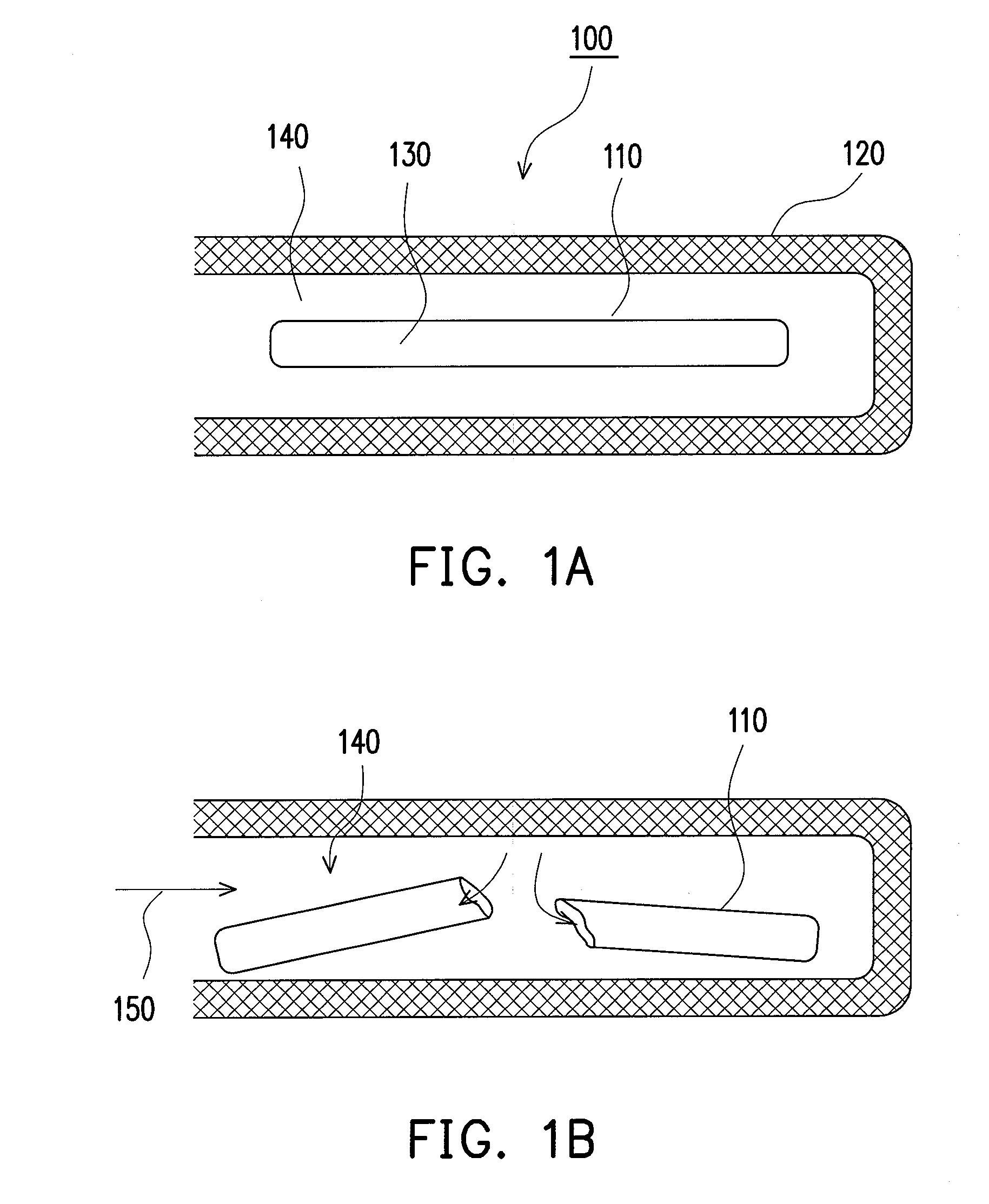
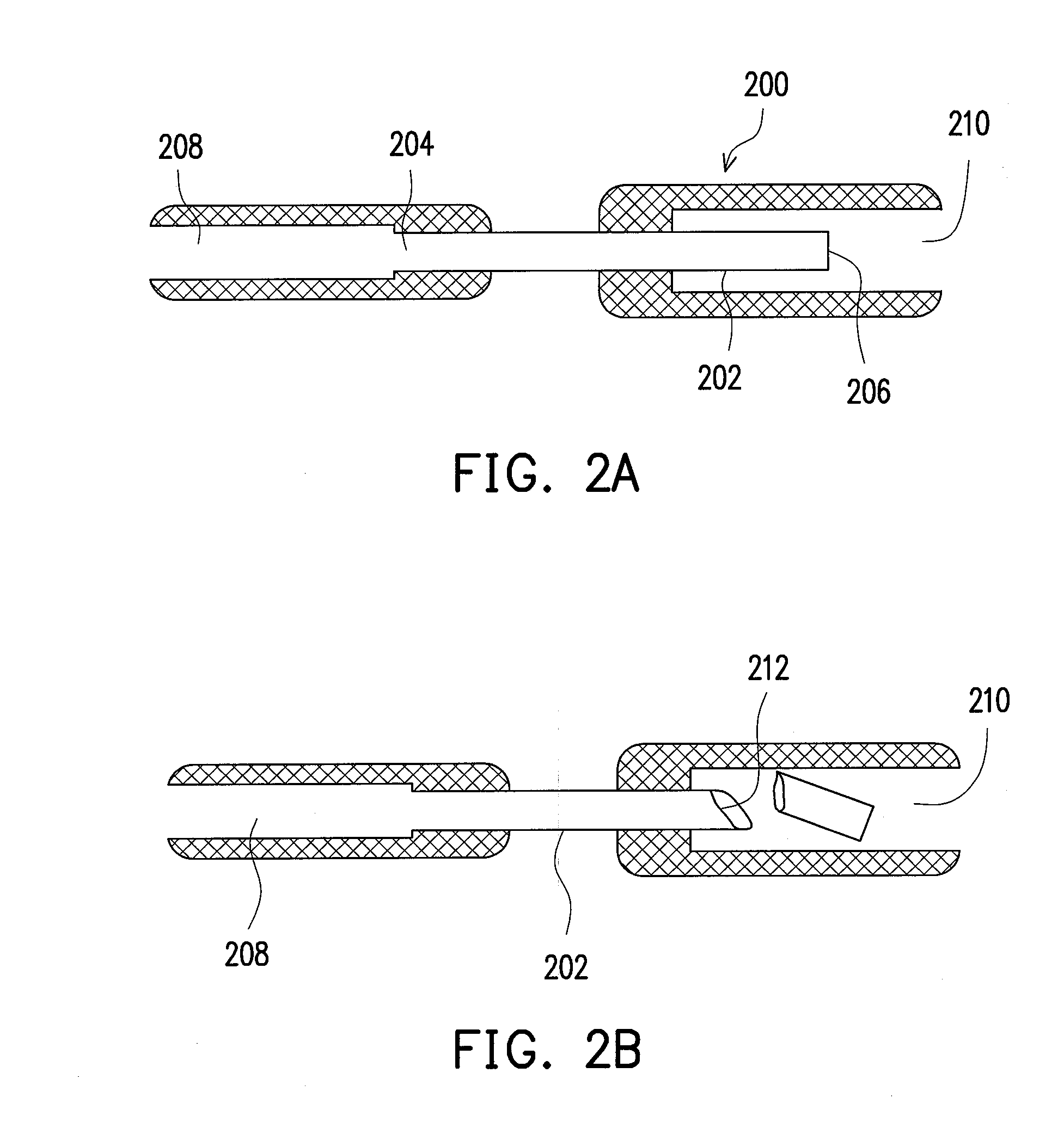
[0013]Accordingly, the present invention is directed to a fluidic device and a method thereof for sealing a proper amount of fluid with a brittle material. By moving an adsorbate through an external adsorption force, the brittle material for pre-sealing is broken, and the fluid flows out to interact with the external environment to generate a pump reaction. In addition, the invention may also be used for storing a liquid reagent in a device for a long time. Thereby, the fluidic device can be made small and portable.

Problems solved by technology

Conventional biochemical reaction experiments are a kind of labour-intensive work.
However, the mechanical arm is high in cost, inconvenient to carry, and thus limited in application.
The acoustics capable of generating power through the vibration of a solid-liquid interface is complicated in application and still under study.
The driving force is related to the ion strength and pH value of the liquid, and is difficult to be widely applied.
However, many heterogeneous immunoassays cannot be implemented by means of a strip, and still needs to be handled in centralized laboratories.
Besides, the analysis usually lasts for several hours due to the limitation of the quality transmission for diffusion on the microtiter plate.
However, these equipments are large in size, high in price, and restrict the microfluidic chip only to be used in the centralized laboratories, so the advantages of the microfluidic chip are greatly weakened.

Method used


Image

  • Fluidic device
  • Fluidic device
  • Fluidic device

Examples


first embodiment

[0038]Referring to FIGS. 3A and 3B, a fluidic device according to a first embodiment of the present invention is shown. The fluidic device 300 includes a main body 301 with, for instance, a T-shaped groove composed of a groove 302 and a groove 304 perpendicular thereto. A capillary 310 made of a brittle material is placed in the groove 302, and a portion thereof is disposed in the groove 304, i.e., protruding in the groove 304. The capillary 310 is, for example, a glass capillary, or a fragile structure made of quartz, ceramic, plastic, or a composite material. A closed space 315 inside the capillary 310 seals a proper amount of vacuum, compressed air, gas, liquid reagent, or fluid. The fluidic device 300 further includes a magnetic actuating unit set composed of a first magnetic unit 320 and a second magnetic unit 330. The first magnetic unit 320 is an external actuating unit made of, for example, a magnetic or electromagnetic coil, and the second magnetic unit 330 is an adsorbate ...

second embodiment

Sandwich Assay

[0052]Referring to FIG. 5, a schematic structural view of a fluidic device according to a second embodiment of the present invention is shown. The fluidic device 500 includes a main body 505 with a reaction channel 510 of a multi-bent structure. A capture antibody zone 511, a scrap zone 513, and an actuating zone 515 are disposed in the multi-bent structure. Further, a capture antibody array 514 is disposed in the capture antibody zone 511. Vacuum tubes 530,532, 534, and 536 in different sizes are disposed in the actuating zone 515, and each have a portion protruding in the actuating zone 515. The protruding portions of the vacuum tubes 530, 532, 534, and 536 are, for example, glass capillaries, or fragile structures made of quartz, ceramic, plastic, or a composite material. In this embodiment, the protruding portions of the vacuum tubes 530, 532, 534, and 536 are broken according to a designed time sequence, so as to generate an adsorption force for drawing an inspect...

third embodiment

Nucleic Acid Molecule Inspection (Glass Microbead) Chip Design

[0060]Referring to FIG. 6A, a schematic structural view of a fluidic device (an inspection chip herein) according to a third embodiment of the present invention is shown. The inspection chip 600 includes an L-shaped reaction channel 605. The reaction channel 605 includes a quantitative zone 610, a reaction zone 620, and an actuating zone 630. The quantitative zone 610 is connected to the reaction zone 620 through a network micro-structure zone 615, and the reaction zone 620 is connected to the waste liquid collection zone 630 through a network micro-structure zone 625. As shown in FIG. 6B, a plurality of particularly processed glass microbeads 622 is disposed in the reaction zone 620. Thus, when targets to be inspected in a sample pass by, each glass microbead 622 will be integrated with the targets (i.e., targets 624 in the figure) and capture the targets in the chamber. Molecules not to be inspected or impurities (i.e.,...


PUM


Abstract

A fluidic device is provided for sealing a proper amount of fluid with a brittle material. By moving an adsorbate through an external adsorption force, the brittle material for pre-sealing is broken, and the fluid flows out to interact with the external environment to generate a pump reaction. In addition, the invention may also be used for storing a liquid reagent in a device for a long time. Thereby, the fluidic device can be made small and portable.

Description

CROSS-REFERENCE TO RELATED APPLICATION[0001]This application claims the priority benefit of Taiwan application serial no. 97122692, filed on Jun. 18, 2008. The entirety of the above-mentioned patent application is hereby incorporated by reference herein and made a part of this specification.BACKGROUND OF THE INVENTION[0002]1. Field of the Invention[0003]The present invention generally relates to a fluidic device, in particular, to a magnetically actuated fluidic device.[0004]2. Description of Related Art[0005]Conventional biochemical reaction experiments are a kind of labour-intensive work. Scientists carry out biochemical reactions on reagents with test tubes and burettes in a lab, mainly for controlling the reagent delivery, mixing a reagent with a checked body, and waiting for a required time to perform a reaction or separation / extraction. A lab of certain scale has already employed mechanical arms to carry out the reactions, so that the labour force is greatly reduced, and the r...

Claims


Application Information

Patent Timeline
Patent Type & Authority Applications(United States)
IPC IPC(8): B81B7/04F15C3/00
CPCB01L3/5027B01L3/50273B01L3/502784B01L2200/0605B01L2200/0621B01L2200/16B01L2300/0816B01L2300/0867B01L2400/043B01L2400/0487B01L2400/049B01L2400/0672B01L2400/0683F04B19/006F16K99/0001F16K99/003F16K99/0046F16K2099/0084Y10T137/1632Y10T137/212Y10T137/2213Y10T137/2224
Inventor WENG, KUO-YAOCHEN, CHIEN-ANKO, CHENG-YUSU, CHIH-HSIENCHOU, NIEN-JENYANG, CHIH-WEN
Owner IND TECH RES INST
Features
  • Generate Ideas
  • Intellectual Property
  • Life Sciences
  • Materials
  • Tech Scout
  • Unparalleled Data Quality
  • Higher Quality Content
  • 60% Fewer Hallucinations
Learn More