Cooling system for forming mold and method of cooling forming mold

a cooling system and mold technology, applied in the field of art for cooling a mold, can solve the problems of reducing the quality of molten metal, reducing the working atmosphere, and reducing the humidity in the factory, so as to prevent the increase of back pressure and improve the cooling performan

Inactive Publication Date: 2009-12-24
TOYOTA JIDOSHA KK
View PDF0 Cites 18 Cited by
  • Summary
  • Abstract
  • Description
  • Claims
  • Application Information

AI Technical Summary

Benefits of technology

[0016]In accordance with the present invention, in a forming mold equipped with a cooling channel through which a refrigerant including a cooling gas and an atomized coolant liquid passes, the refrigerant of which oxygen concentration is lowered is fed to the cooling channel, thereby preventing the occurrence of rust or scale at the wall of the cooling channel caused of the refrigerant passing therethrough.
[0017]Further, in accordance with the present invention, in a forming mold equipped with a cooling channel through which a refrigerant including a cooling gas and an atomized coolant liquid passes, the refrigerant in the cooling channel is forcedly exhausted, thereby preventing the increase of the back pressure due to the evaporation of the coolant liquid. Therefore, the evaporation of the coolant liquid is prevented form lowering and the refrigerant passing through the cooling channel is regulated, which results in improving the cooling performance.

Problems solved by technology

The vapor is emitted around the mold, which causes the heightening of humidity in the factory, so that the working atmosphere lowers.
Particularly, with respect to a casting mold, the heightened humidity lowers the quality of molten metal.
Further, the turbulence of the coolant occurs and unfortunately the equal cooling is blocked.
Thus, there occurs rust that degrades the mold or scale that lowers the cooling efficiency.
Therefore, the elimination of the dissolved oxygen may fail to prevent the rust.

Method used


Image

  • Cooling system for forming mold and method of cooling forming mold
  • Cooling system for forming mold and method of cooling forming mold

Examples


Embodiment Construction

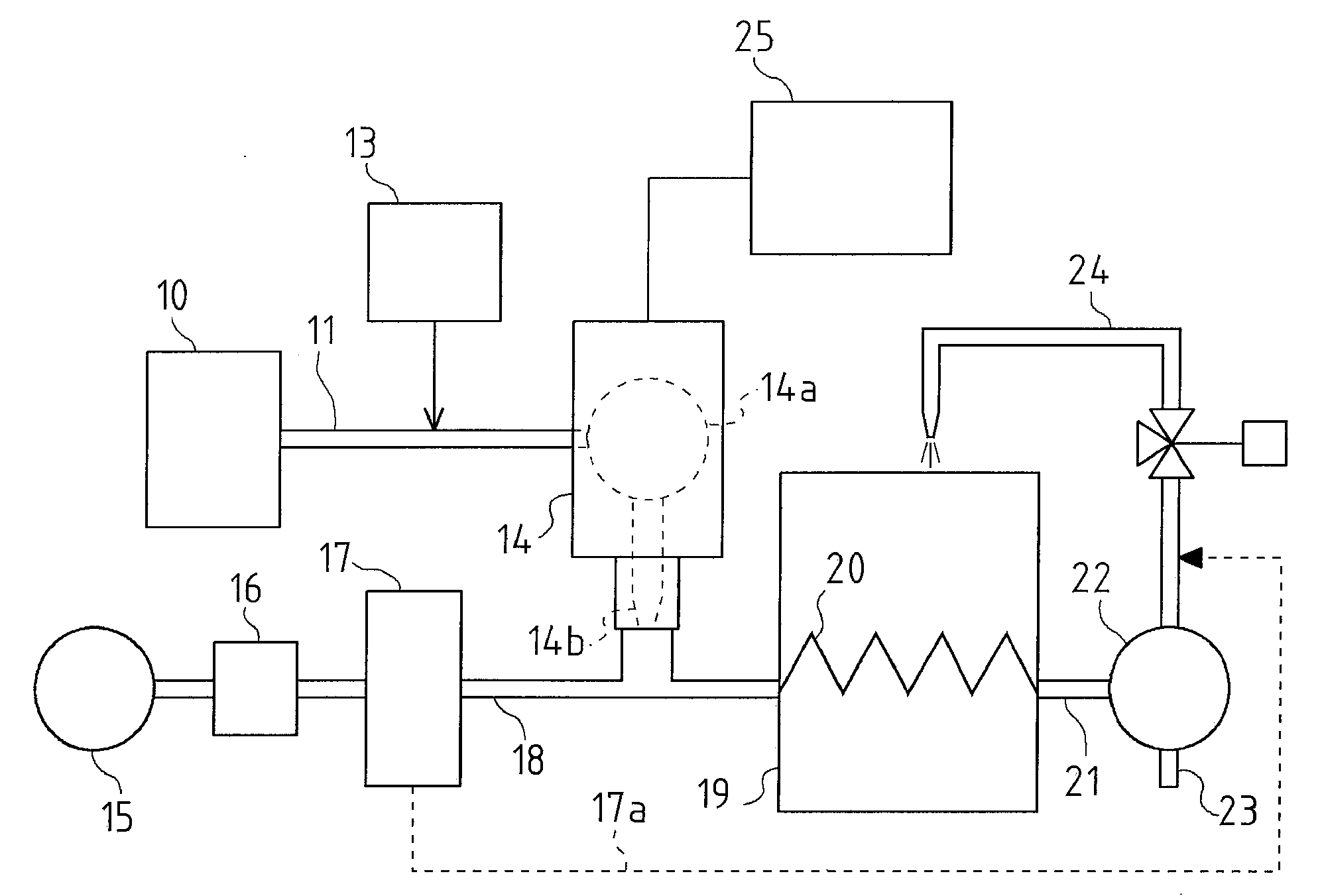
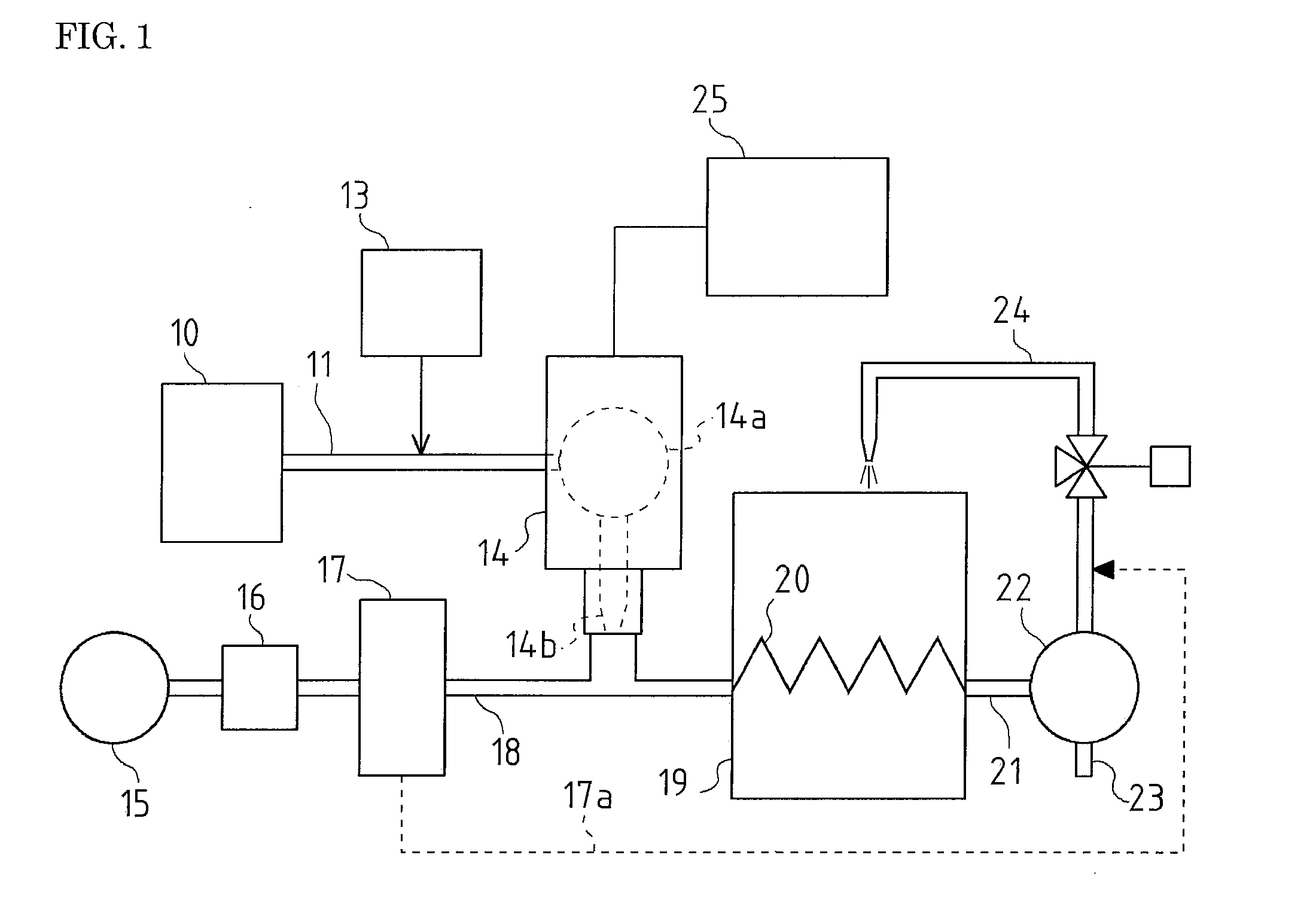
[0030]Referring FIG. 1, a forming mold 19 will be described below, which is one embodiment of a forming mold provided with a cooling system in accordance with the present invention.

[0031]The forming mold 19 provided with the cooling system includes a cooling channel 20 through which a refrigerant for cooling the mold 19 passes.

[0032]The refrigerant passing through the cooling channel 20 includes a cooling gas and an atomized coolant liquid (hereinafter called ‘atomized water’).

[0033]The cooling gas is an air of which oxygen concentration is lowered, namely a gas in which the oxygen is eliminated from the air. The atomized water is at least the atomized pure water at the introduction of the cooling channel 20.

[0034]The refrigerant is fed to the mold 19 through a liquid-feeding channel 11 and a gas-feeding channel 18.

[0035]The liquid-feeding channel 11 includes a water tank 10 for storing the pure water as the coolant liquid and atomizing means 14 for pumping up the coolant liquid sto...


PUM

PropertyMeasurementUnit
concentrationaaaaaaaaaa
pressureaaaaaaaaaa
humidityaaaaaaaaaa

Abstract

In a forming mold equipped with a cooling channel for circulation of a refrigerant composed of a cooling gas and a atomized cooling liquid, any increase of back pressure attributed to evaporation of the refrigerant fed to the cooling channel is inhibited to thereby attain cooling acceleration, and further any occurrence of rust or scale by the refrigerant circulated through the cooling channel is prevented. Accordingly, a channel for supply of the refrigerant to the cooling channel of the forming mold is provided with air pressure source for trapping of air in the supply channel and pressure feeding of the same; oxygen separation means for separation removal of oxygen from the pressure fed air to thereby lower the oxygen concentration of the air; and atomizing means for spraying of the cooling liquid into the air with oxygen concentration lowered. The oxygen separated from the air by the oxygen separation means is returned to the refrigerant forcedly emitted from the cooling channel by means of forced exhaust means.

Description

TECHNICAL FIELD [0001]The present invention relates to an art for cooling a forming mold.BACKGROUND ART [0002]It is known that the conventional art for cooling of a forming mold, in which the forming mold includes a cooling channel and an atomized coolant liquid as a refrigerant is flowed with compressed air in the cooling channel (see JP-63-299848A). In this conventional cooling art, the refrigerant consisting of the coolant liquid and the compressed air is flowed into the cooling channel, and the air blow and heat of evaporation of the coolant liquid make the forming mold cool, in which the refrigerant passes through the cooling channel taking heat from surroundings.[0003]It is also known that the conventional cooling for the forming mold, in which a flux of the atomized coolant liquid is controlled for adjustment of cooling (see JP-H11-170257A).[0004]In the both conventional cooling art, the exhaust gas from the cooling channel contains a lot of water vapor. The vapor is emitted ...

Claims


Application Information

Patent Timeline
Patent Type & Authority Applications(United States)
IPC IPC(8): B22D41/005B22C9/00
CPCB22C9/065B22D17/2218B29C33/046B29C2035/1691B29C35/16B29C45/73B29C35/007
Inventor FURUKAWA, YUICHI
Owner TOYOTA JIDOSHA KK
Why Eureka
Try Eureka