Rotation detection device and rotation detector equipped bearing assembly

a technology of rotating detector and detection device, which is applied in the direction of digital computer details, instruments, transportation and packaging, etc., can solve the problems of high manufacturing cost, high sensitivity, and difficulty in securing rotation pulses with high resolving power, so as to increase safety and maneuverability of automotive vehicles, high sensitivity, and high sensitivity.

Active Publication Date: 2009-12-24
NTN CORP
View PDF7 Cites 74 Cited by
  • Summary
  • Abstract
  • Description
  • Claims
  • Application Information

AI Technical Summary

Benefits of technology

[0031]According to the above described construction, since the rotation detection device of the above described construction is mounted on the bearing, the number of component parts and assembling steps used in the machine that includes the bearing assembly, and compactization can be accomplished while securing a functionality of detecting the absolute angle. By way of example, when this bearing assembly is applied to an automotive vehicle as a wheel support bearing assembly, a minute difference in rotation between left and right wheels and change in rotational speed can be detected with high sensitivity and, therefore, a highly sophisticated vehicle control is possible with the utilization of this signal and the safety and maneuverability of the automotive vehicle can be increased. For example, the precision with which the rotational speed of each of the left and right vehicle wheels can be increased and predication of the amount of skid of a tire during cornering can be facilitated, leading to increase in precision of a skid preventive apparatus and a vehicle attitude stabilizing device. Also, a slight advance and / or backward movement at the time of starting on a slope can be detected together with the direction of rotation of each vehicle wheel and, by performing an optimum brake control appropriate to a condition, the easiness of drive of the automotive vehicle can be increased. Accordingly, there is no need to employ the magnetic sensors in proximity of the magnetic encoders in order to increase the detecting precision and, therefore, assemblage and processing of the rotation detection device can be simplified to thereby reduce the manufacturing cost.

Problems solved by technology

However, the rotation detection devices of the structure discussed hereinabove have the following problems.
While a resolver is currently largely employed for the detection of rotational position of, for example, a motor, there is a problem that the manufacturing cost is high.
In each of the rotation detection devices of the structure discussed hereinabove, the type in which a magnetic encoder is employed has a difficulty in detecting the absolute angle and, also, securing rotation pulses with high resolving power.
In the case of the rotation detection device disclosed in the Patent Document 1, the structure is complicated and also the absolute angle cannot be detected in a non-rotating condition.
The rotation detection device disclosed in the Patent Document 2 is of a system similar to that employing the resolver and is an example in which influence brought about by misalignment relative to the rotor is reduced, but there is a problem that a complex coil is needed.

Method used


Image

  • Rotation detection device and rotation detector equipped bearing assembly
  • Rotation detection device and rotation detector equipped bearing assembly
  • Rotation detection device and rotation detector equipped bearing assembly

Examples


first embodiment

[0083]The first embodiment shown in FIG. 9 is a so-called third generation type and is used for supporting a vehicle drive wheel. The inner member 52 is made up of two components, that is, a hub unit 57 and an inner ring 58 mounted on an outer periphery of an inboard end of a hub axle 57a of the hub unit 57, with the rolling surfaces 56 formed respectively in the outer periphery of the hub axle 57a of the hub unit 57 and that of the inner ring 58. The hub axle 57a of the hub unit 57a has a center bore 57c defined therein for passage therethrough of a stem portion of a constant velocity universal joint. The inner ring 58 is mounted on a radially inwardly stepped area formed in the hub axle 57a of the hub unit 57 and is fixed to the hub unit 57 by means of a crimped portion 57aa provided at an inboard end of the hub axle 57a. The hub unit 57 has an outer periphery formed with a wheel mounting flange 57b positioned in the vicinity of an outboard end thereof, and the vehicle wheel and a...

third embodiment

[0106]FIGS. 16 and 17 illustrate a fourth preferred embodiment of the present invention. This embodiment is such that in the third embodiment shown in and described with reference to FIGS. 14 and 15, the inboard sealing element 61 for the bearing space is positioned outwardly of the magnetic encoders 2A and 2B. In other words, as best shown in FIG. 16, the sealing element 61 such as, for example, a contact seal element is provided between an annular sensor mounting member 72, fitted to the outer member 51, and the inner ring 58. As best shown in FIG. 17, a cord 19 is drawn outwardly from the sensor side unit 1A in a tangential direction with respect to the bearing assembly.

[0107]In the case of this construction, because of the presence of the sealing element 61, the magnetic encoders 2A and 2B are sealed from the outside space and any undesirable ingress of, for example, foreign matter in between the magnetic encoders 2A and 2B and the sensor side unit 1A can be avoided. Other struc...

fifth embodiment

[0110]FIGS. 20 and 21 illustrate a sixth preferred embodiment of the present invention. This embodiment is such that in the example shown in and described with particular reference to FIGS. 18 and 19, the magnetic encoders 2A and 2B and the sensor side unit 1A are opposed to each other in the axial direction. Other structural features and advantages brought about thereby are similar to those afforded by the fifth embodiment shown in and described with particular reference to FIGS. 18 and 19.

[0111]The wheel support bearing assembly shown in FIG. 22 showing a seventh preferred embodiment of the present invention is an example of a so-called fourth generation type, in which the inner member 52 is made of a hub unit 57A and a constant velocity universal joint outer ring 81.

[0112]The constant velocity universal joint 80 is of a structure in which a plurality of axially oriented raceway grooves are formed in a spherical outer surface of the inner ring 82 and a similarly spherical inner su...


PUM


Abstract

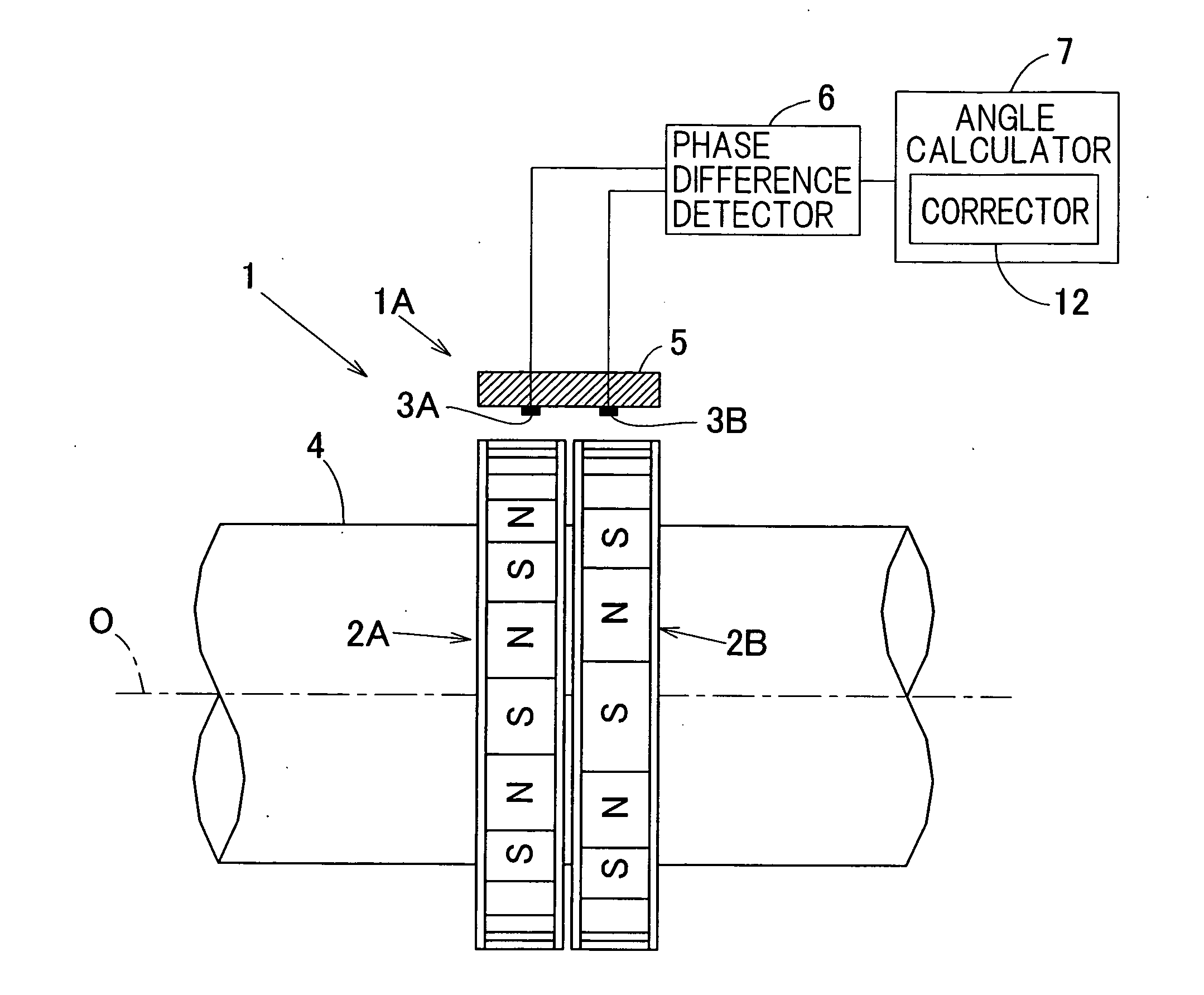
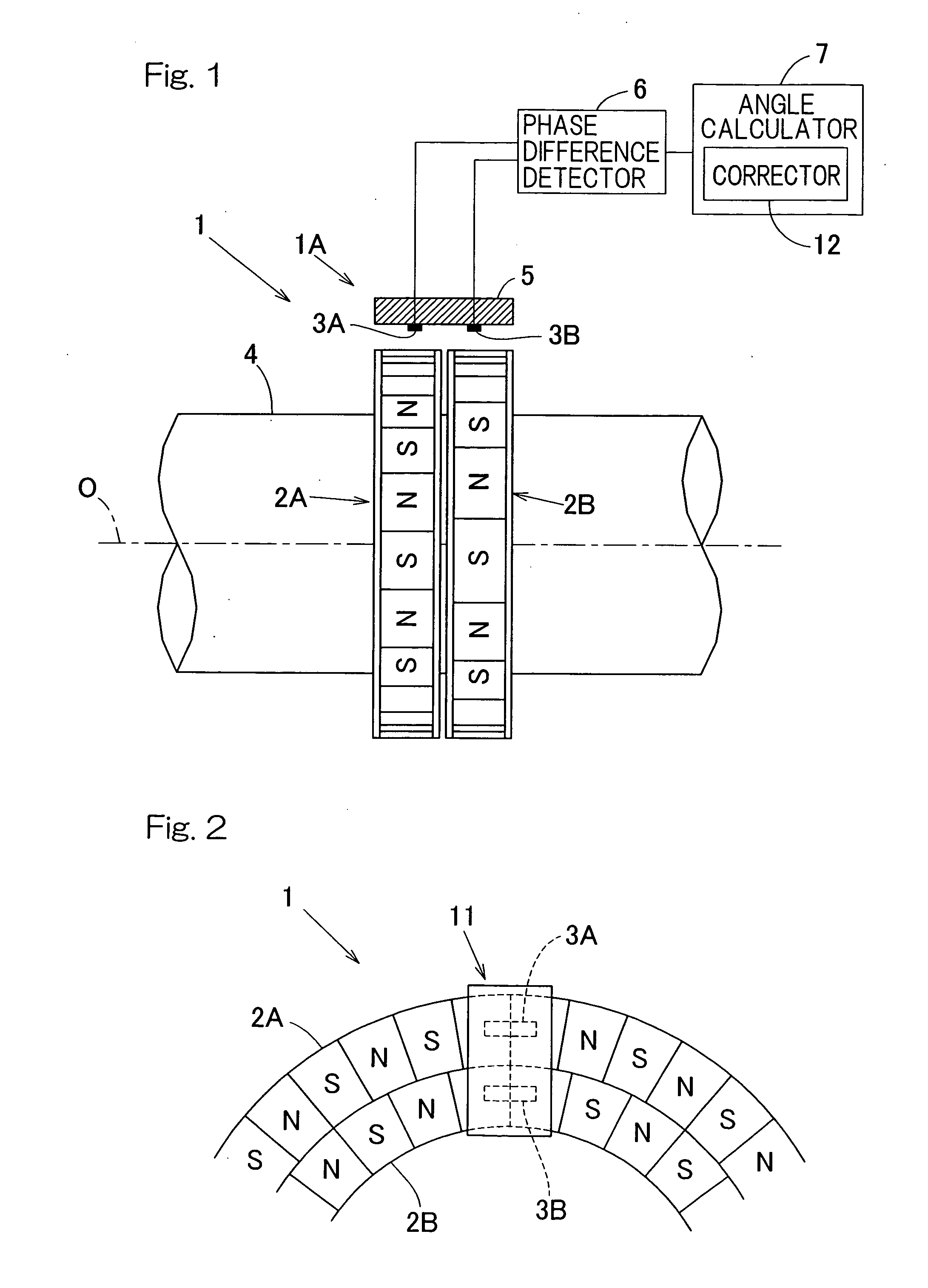
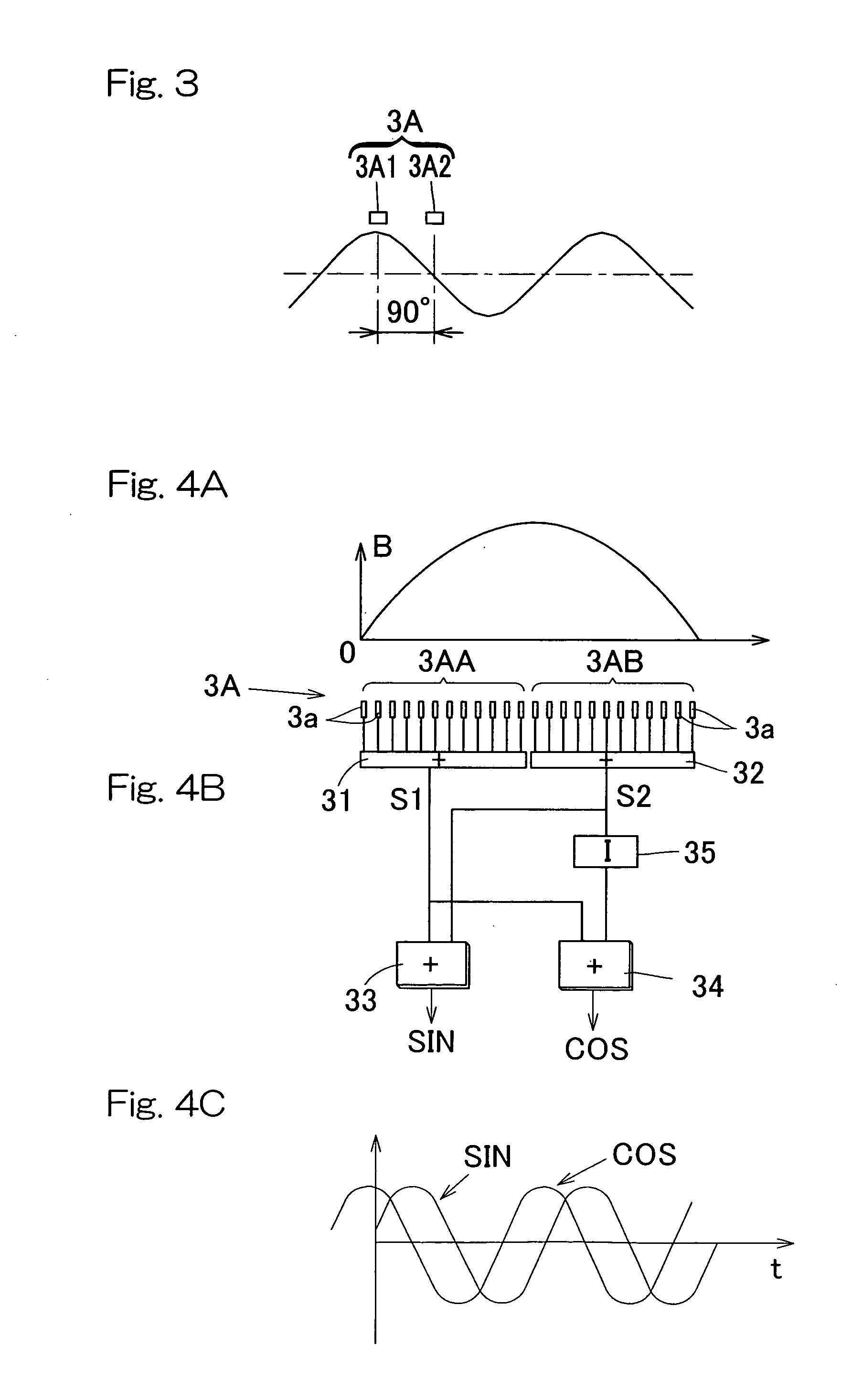
There is provided a rotation detection device 1 which includes a plurality of magnetic encoders (2A, 2B) of a ring shape arranged coaxially and having different numbers of magnetic poles, a plurality of magnetic sensors (3A, 3B) each operable to detect the magnetic field of the corresponding magnetic encoder and having a function of detecting positional information within a single magnetic pole of the corresponding magnetic encoder, a phase difference detector (6) for determining the phase difference of magnetic field signals detected respectively by the magnetic sensors (3A, 3B), and an angle calculator (7) for calculating an absolute rotation angle of the magnetic encoders based on the detected phase difference.

Description

CROSS REFERENCE RELATED TO APPLICATIONS[0001]This application is based on and claims priority to the Japanese Patent Application No. 2007-043735, filed Feb. 23, 2007, and the Japanese Patent Applications No. 2007-260721 and No. 2007-260722, both filed Oct. 4, 2007, which are incorporated by reference in its entirety into this application.BACKGROUND OF THE INVENTION[0002]1. Field of the Invention[0003]The present invention relates to a rotation detection device that is used in various machines and equipments for detecting the angle of rotation and, in particular, for detecting the angle of rotation for the purpose of controlling the rotation of various motors, and also to a rotation detector equipped bearing assembly having such rotation detection device mounted therein.[0004]2. Description of the Prior Art[0005]In order to accurately detect the status of rotation of a rotary body used in, for example, an automotive vehicle or a railway vehicle, a desire has often arisen to detect a ...

Claims


Application Information

Patent Timeline
Patent Type & Authority Applications(United States)
IPC IPC(8): G01B7/30G01B15/00
CPCF16C41/007G01D5/2452G01D5/2457G01P3/443G01P3/446G01P3/487F16C2326/02F16C33/76F16C19/06F16C19/186F16C19/187F16C19/386F16C2326/10G01P13/04F16C2300/02
Inventor TAKAHASHI, TORUUENO, SHINTAROU
Owner NTN CORP
Why Eureka
Try Eureka