Optical Information Recording Method, Optical Information Reproduction Method and Optical Disk Device

a technology of optical information and recording method, applied in the field of information recording method, can solve the problems of equalization processing with a fixed group delay characteristic, inability to compensate for the distortion of the reproduced signal, etc., to achieve high transfer rate, increase the density of record information, and secure quality

Inactive Publication Date: 2009-12-24
KONINKLJIJKE PHILIPS NV
View PDF12 Cites 15 Cited by
  • Summary
  • Abstract
  • Description
  • Claims
  • Application Information

AI Technical Summary

Benefits of technology

[0012]The present invention enables both of the securing of quality in the information reproduction through the PRML processing from a recording medium and the evaluation of reproduced signals by use of ML decoder scheme such as the PRML processing in the high-speed recording and reproduction. As a result, for the S / N deterioration of signals or the like due to the restriction of the signal transmission characteristic and the increase in the density of record information, the recording parameter and the servo parameter can be stably adjusted through the stable information reproduction and the detection of the signal edge phase shift by use of the PRML.
[0013]Hence, the high-speed recording and reproduction by realizing a high transfer rate for the to-be-recorded information and reproduced information as well as various adjustments can be conducted at one and the same speed. Heat generated due to increase in the motor load caused by the speed change can be reduced and occurrence of the rotary regulation wait time associated with the speed change can be suppressed. It is hence possible to implement the stabilization and power saving in the recording learning operation as well as to minimize the learning time.

Problems solved by technology

Hence, distortion takes place also in the reproduced signal obtained from the recording medium.
However, the adaptive equalization processing with a fixed group delay characteristic as described above cannot compensate for the distortion of the reproduced signal.
This accordingly causes a binarization processing error in the viterbi decoding processing.

Method used


Image

  • Optical Information Recording Method, Optical Information Reproduction Method and Optical Disk Device
  • Optical Information Recording Method, Optical Information Reproduction Method and Optical Disk Device
  • Optical Information Recording Method, Optical Information Reproduction Method and Optical Disk Device

Examples


embodiment 1

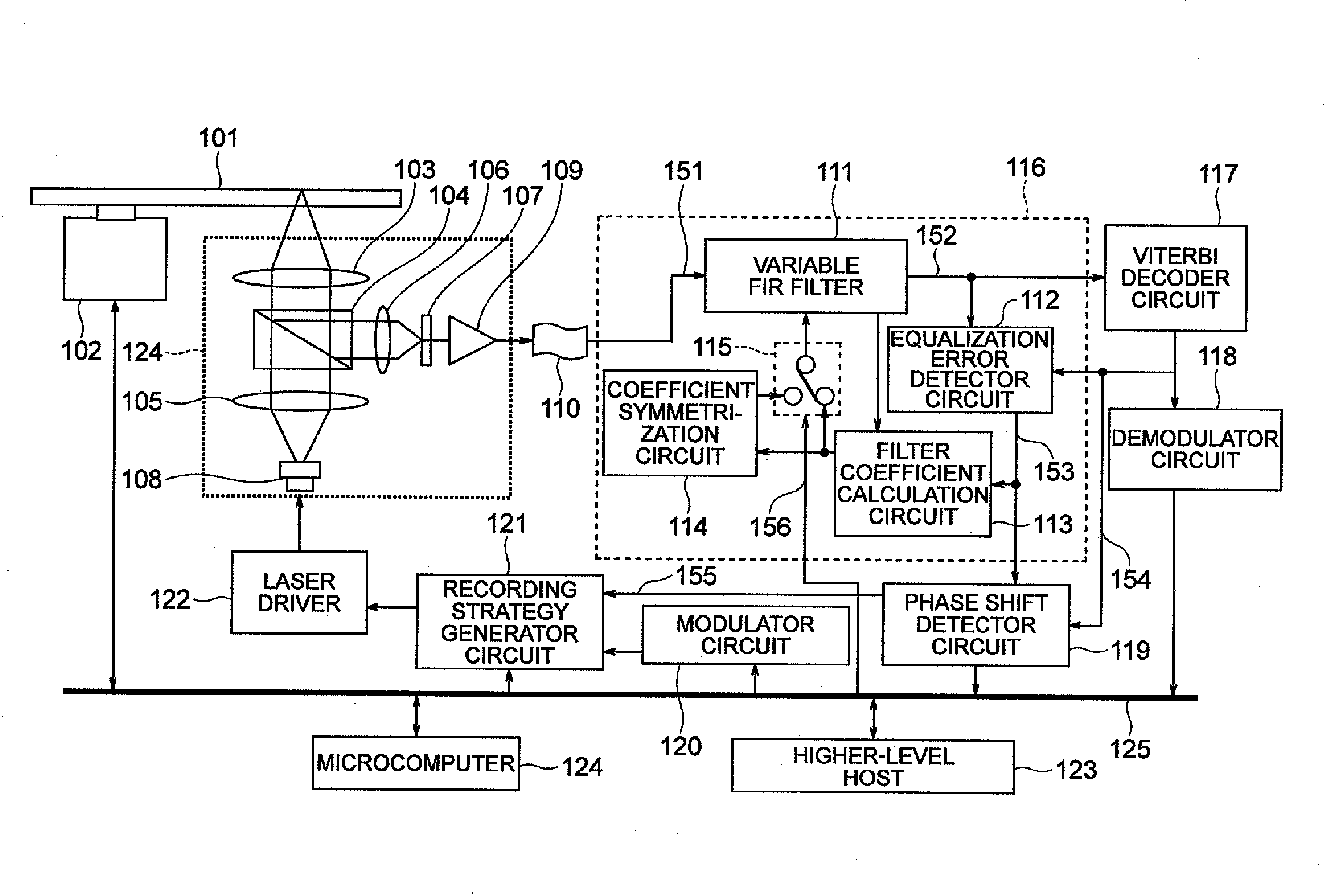
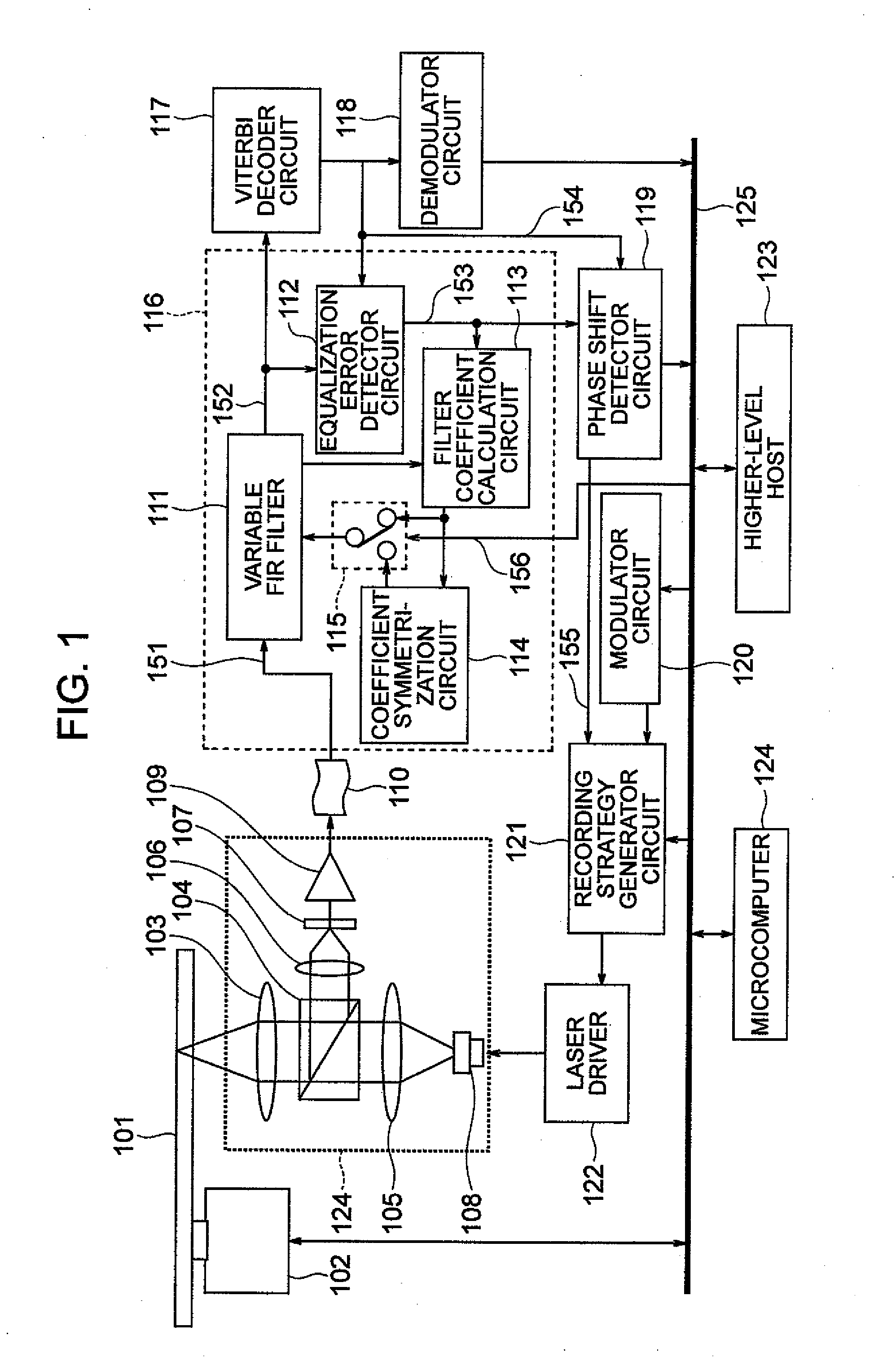
[0041]FIG. 1 shows a system configuration of the first embodiment.

[0042]Information data outputted from a higher-level host 123 via a signal bus 125 is modulated by a modulator circuit 120 into a disk record signal. A recording strategy generator circuit 121 generates the recording strategy described above by use of a disk record signal, a pulse timing setting value 155 outputted from a phase shift detector circuit, recording power setting from a microcomputer 124, and the like. A laser driver 122 drives a laser 108 according to the recording strategy. Laser light radiated from the laser 108 records via a collimation lens 105 and an objective 103 a mark on an optical disk 101. As a result, data is recorded on the optical disk 101.

[0043]Next, in an operation to reproduce data recorded on the optical disk 101, reflected light obtained by radiating laser light onto the optical disk 101 is collected via a beam splitter 104 by a condenser 106 onto a photoelectric conversion element 107 t...

embodiment 2

[0069]Next, FIG. 13 shows a system configuration in a second embodiment of the present invention. In FIG. 13, the elements and blocks having the same functions as those of FIG. 1 are assigned with the same reference numerals, and description thereof will be here avoided.

[0070]In FIG. 13, 1301 indicates an FIR filter for which the coefficient values are fixed. The taps of the reproduction clock period and structure to calculate the coefficient values are similar to those of the first embodiment. However, in the present embodiment, since the output from the equalization error detector circuit in the succeeding stage is used to adjust edge timing of the recording strategy, the coefficients of the respective taps are set to fixed values such that the values are symmetric in the time-axis direction.

[0071]1302 indicates a target value update circuit to update the target equalization characteristic employed in the viterbi decoding shown in Table 1 described above.

[0072]1303 is a symmetriza...

embodiment 3

Application to Verifying Operation

[0086]FIG. 17 shows a circuit configuration of the third embodiment of the present invention. In FIG. 17, the elements and blocks having the same functions as those of FIGS. 1 and 13 are assigned with the same reference numerals, and description thereof will be here avoided.

[0087]The circuit configuration includes both of the function of the adaptive equalization circuit of the first embodiment and that of the adaptive viterbi decoder circuit of the second embodiment. FIG. 18 shows details of a switch 1701. The switch 1701 conducts, for the equalization target value to calculate the equalization error in the equalization error detector circuit, a changeover operation between an update target value 1353 generated from the equalized output 152 and the binary signal 1352 and a symmetrization target value 1354 obtained by symmetrizing the symmetrization target value 1353. FIG. 18 shows the switch 1701 in detail. In the switch changeover, the update targ...


PUM

PropertyMeasurementUnit
phase shiftaaaaaaaaaa
drive currentaaaaaaaaaa
phase shift magnitudeaaaaaaaaaa

Abstract

When a phase shift is to be evaluated, based on a difference between an output from a waveform equalization circuit to equalize an input reproduced signal to a predetermined target equalization characteristic and the target equalization characteristic, the phase shift of the reproduced signal relative to a channel clock, a group delay characteristic with respect to the frequency of the waveform equalization circuit is fixed. Hence, an equalized waveform as an output from the waveform equalization circuit can preserve phase shift information of the inputted reproduced signal to correctly detect the phase shift of the reproduced waveform using the equalized waveform. It is hence possible to realize, with high precision, optimal value learning of various parameters for the recording, reproduction, and servo by use of the phase shift as an index.

Description

INCORPORATION BY REFERENCE[0001]The present application claims priority from Japanese application JP2008-158624 filed on Jun. 18, 2008, the content of which is hereby incorporated by reference into this application.BACKGROUND OF THE INVENTION[0002]The present invention relates to an information recording method of optically recording information on a recording medium by use of laser light and a recorder using the method.[0003]In a case wherein binary information or information of multivalue more than the binary information is recorded on a recording medium by use of laser light, there is generally required optimization learning for a laser pulse contour, i.e., a so-called recording strategy to record information on the recording medium, which is referred to as recording learning hereinbelow. In the recording learning, a record waveform is reproduced to be evaluated to learn an optimal recording strategy in the system. As evaluation indices, there are employed jitter which is defined...

Claims


Application Information

Patent Timeline
Patent Type & Authority Applications(United States)
IPC IPC(8): G11B7/135
CPCG11B7/00456G11B7/1267G11B20/10009G11B20/10046G11B20/10481G11B20/10194G11B20/10212G11B20/10222G11B20/10055
Inventor NISHIMURA, KOICHIRONAKAMURA, YUSUKE
Owner KONINKLJIJKE PHILIPS NV
Why Eureka
Try Eureka