Radio wave receiving apparatus

Active Publication Date: 2009-12-24
CASIO COMPUTER CO LTD
View PDF11 Cites 8 Cited by
  • Summary
  • Abstract
  • Description
  • Claims
  • Application Information

AI Technical Summary

Benefits of technology

[0010]An object of the present invention is to provide a radio wave receiving apparatus capable of performing tuning processing of an antenna only by adding a simple circuit without providing an accurate oscillation circuit.

Problems solved by technology

When adopting a system which receives actual transmission radio wave for performing the tuning processing in order to automatically adjust the tuning circuit in the radio wave receiving apparatus, there is a problem that the automatic adjustment of the tuning circuit can not be normally performed if the tuning circuit does not exist in the environment that the transmission radio wave can be successfully received.
On the other hand, in a system which generates pseudo transmission radio wave by an oscillation circuit and performs the tuning processing while receiving the transmission radio wave, there is a problem that the oscillation circuit accurately oscillating at same frequency as that of the transmission radio wave needs to be prepared individually.
When the oscillation circuit is provided inside the receiving apparatus, because a crystal oscillator or the like needs to be used for obtaining an accurate oscillation frequency, even if the reception circuit and the like are integrated, it is difficult to mount all of the oscillation circuit on the integrated circuit.
In addition, a configuration which uses a Phase Locked Loop (PLL) circuit to generate an oscillation signal of a predetermined frequency from a reference clock of the integrated circuit may be applied, but a problem that also this configuration needs to prepare an oscillation circuit individually would remain.

Method used


Image

  • Radio wave receiving apparatus
  • Radio wave receiving apparatus
  • Radio wave receiving apparatus

Examples


first embodiment

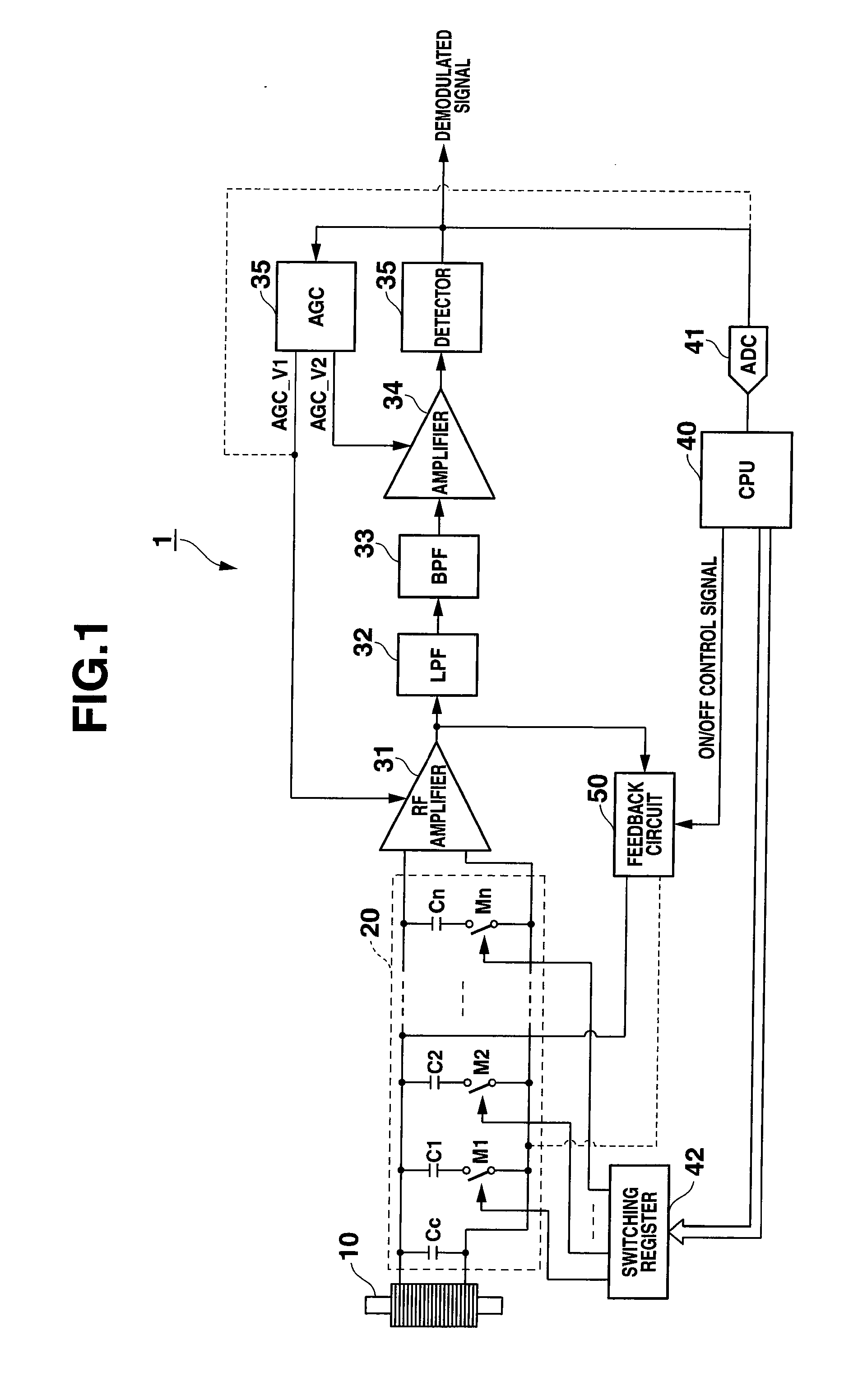
[0025]FIG. 1 is a configuration diagram showing a whole radio wave receiving apparatus according to the first embodiment of the present invention.

[0026]The radio wave receiving apparatus 1 of the embodiment is an apparatus which receives radio wave within a predetermined frequency band and detects a modulation wave included in the radio wave to demodulate it. For example, the radio wave receiving apparatus 1 may be applied to a radio wave clock and the like as a reception circuit which receives standard radio wave of 60 kHz to demodulate a time code by which carrier wave of the standard radio wave is amplitude modulated.

[0027]The radio wave receiving apparatus 1 is equipped with: an antenna 10; a tuning circuit 20 to allow a reception frequency of the antenna 10 to be tuned to an intended frequency; an RF amplifier 31 to amplify the reception signal; a low pass filter 32 and band pass filter 33 which extract a signal within a reception frequency band from the reception signal; an am...

second embodiment

[0078]FIG. 7 shows a configuration diagram showing a whole radio wave receiving apparatus 1A according to the second embodiment of the present invention.

[0079]The radio wave receiving apparatus 1A of the second embodiment is, for example, an apparatus mounted to a cellular phone and the like and receiving a radio wave signal of high frequency, which is configured to be capable of performing self-oscillation to automatically adjust a frequency characteristic of the antenna.

[0080]As shown in FIG. 7, the radio wave receiving apparatus 1A includes: an antenna 60 to receive the radio wave; an antenna frequency adjustment circuit 61 to adjust the frequency characteristic of the antenna 60; an RF amplifier 62 such as a Low Noise Amplifier (LNA) to amplify the reception signal; a frequency converter 64 (for example, mixer) to convert the reception signal to the intermediate frequency; an oscillator 63 to supply a local signal to the frequency converter 64; a band path filter 65 to allow a s...


PUM


Abstract

Disclosed is a radio wave receiving apparatus including: an antenna to receive a radio wave; a tuning member to allow a reception frequency of the antenna to be tuned to an intended frequency, in which tuning member a frequency characteristic is variable; a receiving member to receive a reception signal from the antenna to demodulate a modulation wave; a positive feedback member to perform a positive feedback in a signal path including the tuning member; and a switching member to turn on / off a feedback operation of the positive feedback member.

Description

CROSS-REFERENCE TO RELATED APPLICATIONS[0001]This application is based upon and claims the benefit of priority from the prior Japanese Patent Application No. 2008-163953, filed on Jun. 24, 2008, and the prior Japanese Patent Application No. 2009-105435, filed on Apr. 23, 2009, the entire contents of which are incorporated herein by reference.BACKGROUND OF THE INVENTION[0002]1. Field of the Invention[0003]The present invention relates to a radio wave receiving apparatus equipped with an antenna and a tuning member.[0004]2. Description of Related Art[0005]There has conventionally been a communication apparatus which automatically adjusts a frequency characteristics of a tuning circuit connected to an antenna so as to highly efficiently transmit / receive a radio wave signal of a predetermined frequency (for example, Japanese Patent Application Laid-Open Publication No. 2000-231609, and U.S. Pat. No. 6,177,846).[0006]When adjusting the tuning circuit at the time of receiving in such comm...

Claims


Application Information

Patent Timeline
IPC IPC(8): H04B1/18H01Q7/00
CPCH03J1/0008H03J2200/10H03J2200/06H03J7/02
Inventor SOMEYA, KAORU
Owner CASIO COMPUTER CO LTD
Why Eureka
Try Eureka