Surface mount device

a surface mount device and mounting plate technology, applied in the direction of printed circuit aspects, sustainable manufacturing/processing, final product manufacturing, etc., can solve the problems of large rated wattage and heating value, insufficient heat generation using ceramic packaging alone, harsh conditions for led light source use, etc., to achieve high reliability and simple composition

Inactive Publication Date: 2009-12-31
STANLEY ELECTRIC CO LTD
View PDF6 Cites 24 Cited by
  • Summary
  • Abstract
  • Description
  • Claims
  • Application Information

AI Technical Summary

Benefits of technology

[0025]According to the above-described exemplary surface mount LED device, the dummy soldering pad and the soldering pads that are electrically connected to the electrodes of the LED chip can be formed on the mounting surface of the ceramic package using the above-described structure of the surface mount device. Thus, a surface mount LED device with high reliability that can be used under harsh environmental conditions can be simple in composition according to the disclosed subject matter.

Problems solved by technology

However, because high flux type LEDs are generally driven by a large current, their rated wattages and heating values become large, and also the high flux type LEDs are frequently used under a harsh environment such as high temperature and high humidity and the like, especially when they are used for vehicle lamps, outdoor lighting, etc.
However, when heat generated from the ceramic package should be radiated to the outside, it may not be adequate to radiate the heat using the ceramic package alone.
However, when the LED light source using the ceramic package is mounted on the metallic circuit board based on aluminum having a high thermal conductivity, because the temperature of the LED light source is increased due to an ambient temperature and heat generated from other parts mounted on the circuit board, conditions for use of the LED light source become harsher.
Thus, because a difference between the temperature of the ceramic package during operating the LED light source and the non-operating temperature becomes very large, a difference between coefficients of thermal expansion of the mounting circuit board and the ceramic package causes the ceramic package to experience thermal fatigue.
The thermal fatigue may cause cracks in connection(s) between the mounting circuit board and the ceramic package, and consequently may cause a disconnection between the LED light source and the mounting circuit board.

Method used


Image

  • Surface mount device
  • Surface mount device
  • Surface mount device

Examples


Embodiment Construction

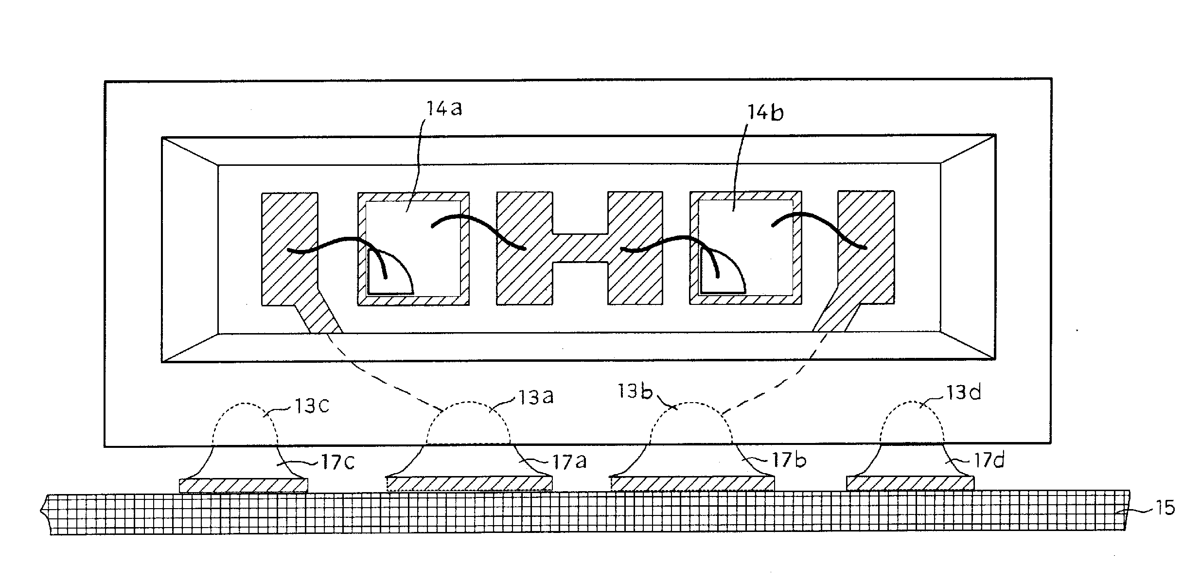
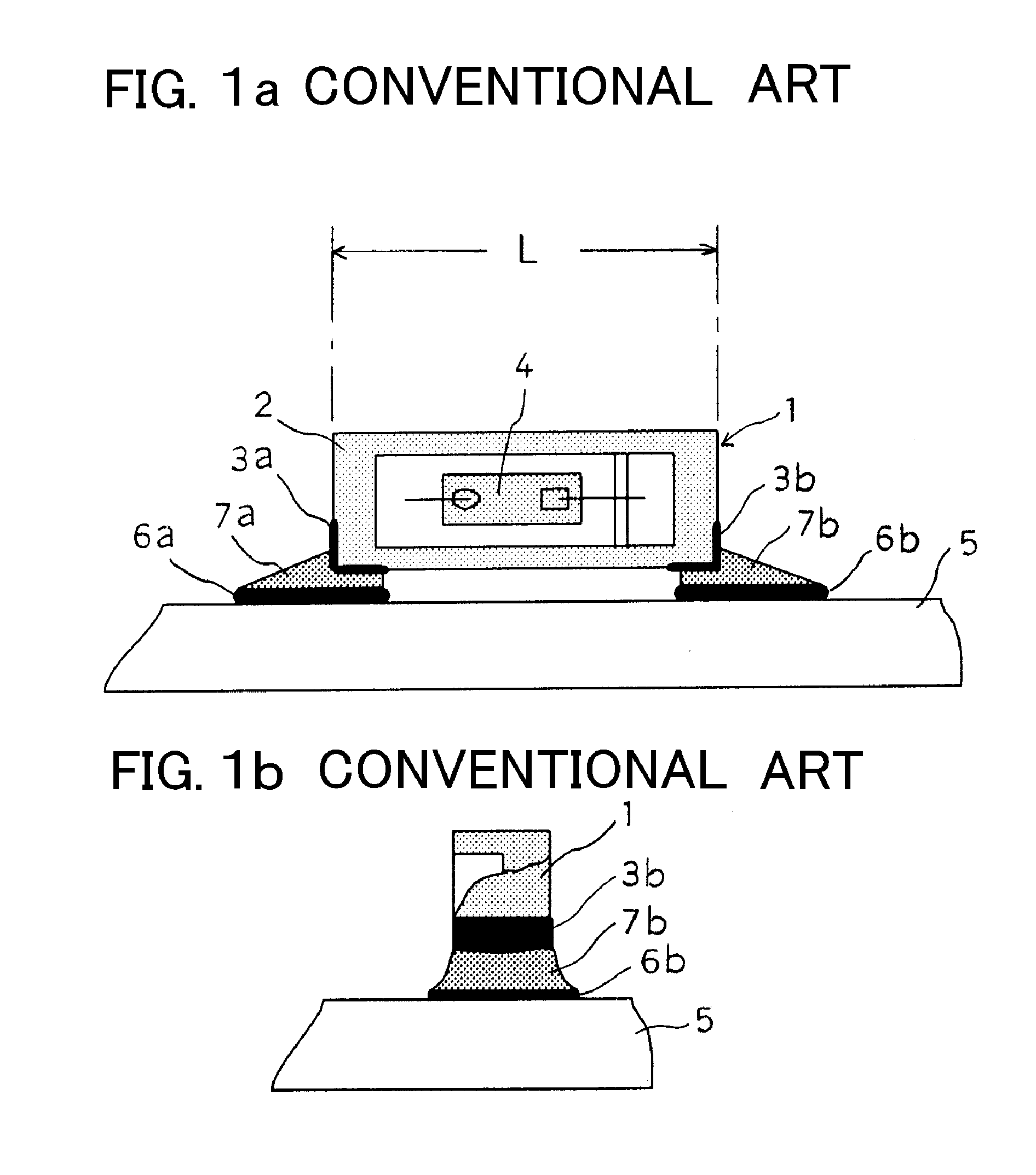
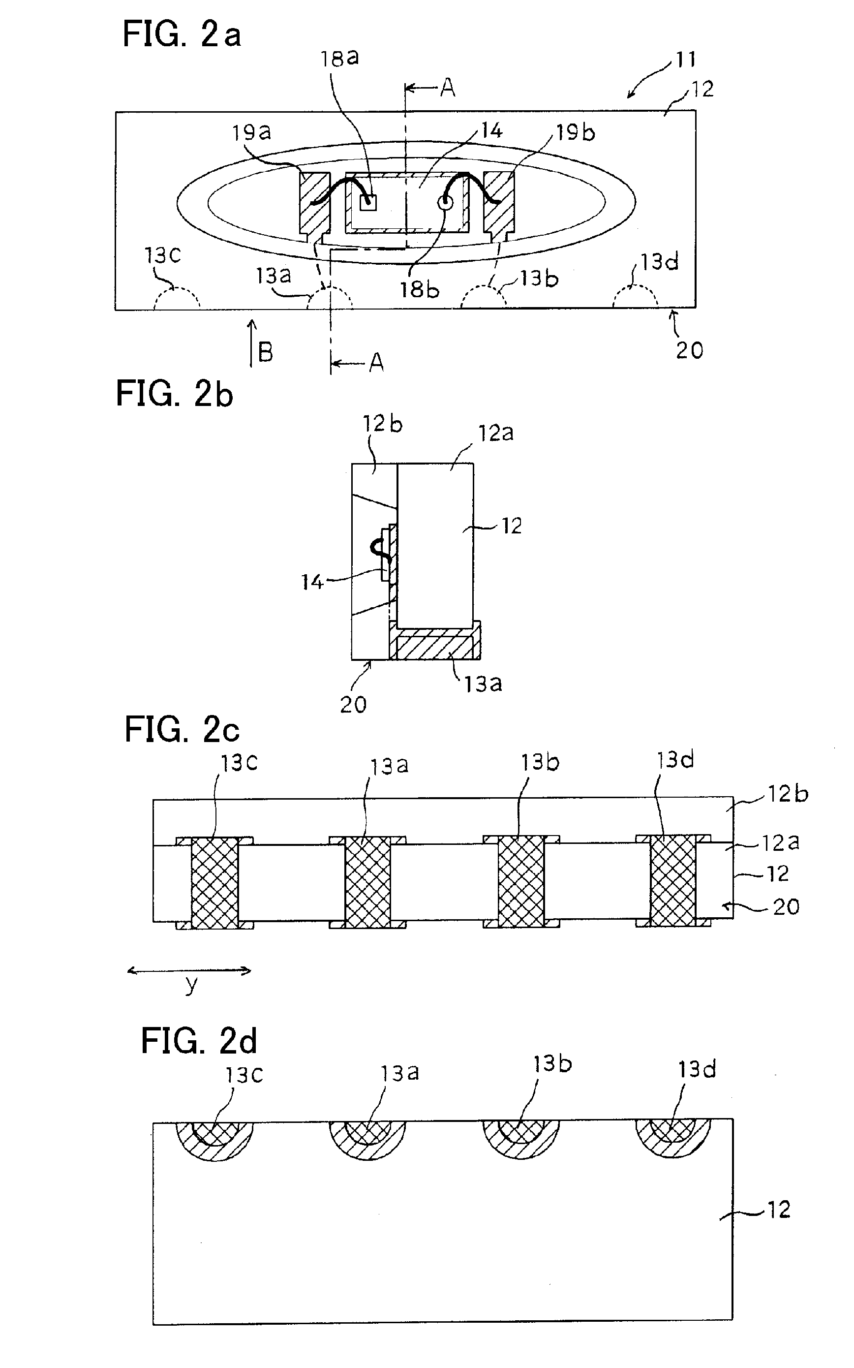
[0035]The disclosed subject matter will now be described in detail with reference to FIGS. 2a-d, 3, and 5 to 8. When a ceramic package is mounted on a rigid mounting circuit board as described above, because thermal expansion coefficients of the mounting circuit board and the ceramic package may be different, a characteristic or problem can exist in which cracks are caused in a soldering connection between the mounting circuit board and the ceramic package, and may occur in particular during environmental tests such as a heat cycle test with a continuous current.

[0036]The characteristic / problem is frequently caused in the following cases.[0037]1. In the case that the ceramic package is large in size according to a product specification.[0038]2. In the case that a residual stress becomes large after soldering with a mercury-free solder having a high melting temperature.[0039]3. In the case that a metallic circuit board is used, such as a glass composite board and a board based on an ...


PUM


Abstract

The disclosed subject matter is directed to a reliable surface mount device using a ceramic package, and includes LED devices that are simply composed and incorporate the use of the surface mount device. The surface mount device can include a ceramic package, a semiconductor optical chip mounted in the package, two soldering pads electrically connected to the chip electrodes and at least one dummy soldering pad located on either side of the soldering pads. Thermal fatigue located at or in the soldering connections connecting the chip electrodes to a mounting board can be reduced because the distance between the soldering pads can be reduced. The dummy soldering pad that is electrically insulated can allow the device to maintain a desirable location with poise during the reflow soldering process that occurs during manufacture, and can also reduce shear stress present at the soldering connections. Thus, the surface mount device and the LED device using the disclosed structure can maintain a high reliability even under harsh environmental conditions.

Description

[0001]This application claims the priority benefit under 35 U.S.C. §119 of Japanese Patent Application No. 2008-168579 filed on Jun. 27, 2008, which is hereby incorporated in its entirety by reference.BACKGROUND[0002]1. Field[0003]The presently disclosed subject matter relates to surface mount devices, and more particularly to reliable surface mount devices including a ceramic package and a semiconductor optical chip such as an LED, a laser diode, a photo diode, etc.[0004]2. Description of the Related Art[0005]Surface mount devices are used for semiconductor light-emitting devices such as an LED and the like and for semiconductor light-receiving devices such as a photo transistor, etc. Surface mount LED devices are used for LCD back light units in mobile phones, digital video cameras, PDAs, etc., since white LEDs have been available on the market. Surface mount LED devices have been recently employed as a light source for vehicle lamps and for general lighting and the general applic...

Claims


Application Information

Patent Timeline
Patent Type & Authority Applications(United States)
IPC IPC(8): H01L33/00H01L33/48H01L33/60H01L33/62
CPCH01L33/486H05K1/111H05K3/3442H05K2201/094H05K2201/09781H01L2224/48227H05K2201/10727H01L2224/48091H05K2201/10106H01L2924/00014Y02P70/50
Inventor NAMIOKA, KAORI
Owner STANLEY ELECTRIC CO LTD
Why Eureka
Try Eureka