Robotic Arms

Inactive Publication Date: 2009-12-31
OLIVER CRISPIN ROBOTICS
View PDF9 Cites 12 Cited by
  • Summary
  • Abstract
  • Description
  • Claims
  • Application Information

AI Technical Summary

Benefits of technology

[0034]For use in surgery, the robotic arm, such as a tip following arm, may be mounted on a highly configurable framework that enables appropriate choice of the point of access and the orientation of axis into the body. Such a framework can be designed to enable a number of tip following robotic arms to be mounted in close proximity

Problems solved by technology

In many situations the former is not practical.
For instance, when considering a 3D volumetric search of a car, it may not be possible to gain access to an appropriate computer model of the car, and the actual condition of the car and contents, such as driver or luggage, would necessarily make the model incorrect.
As a further example, when considering operations within the human body, a model d

Method used


Image

  • Robotic Arms
  • Robotic Arms
  • Robotic Arms

Examples


Embodiment Construction

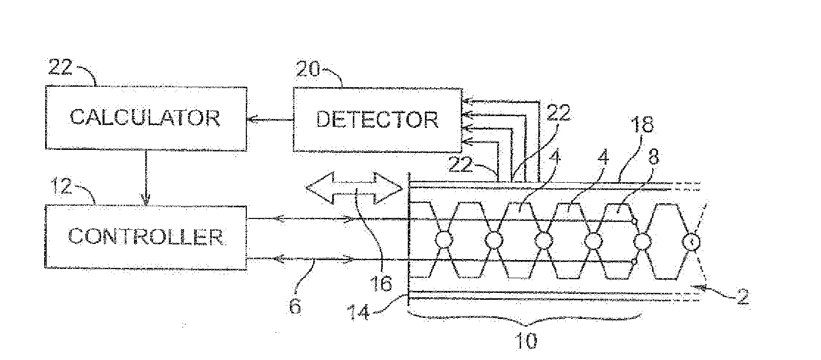
[0050]Referring to FIG. 1, a robotic arm 2 comprises a plurality of articulated links 4. The position of the arm is controlled using controller 6 attached to a link 8 at the end of each segment 10. The control wires 6 are wound in or out by the controller 12 to change the shape of arm. The arm is mounted on the base plate 14 and is moveable on an introduction axis 16 so as to be able to advance or retract as the shape of the arm changes, such that the arm may follow a path in tip following snake-like manner.

[0051]The arm 2 has a tubular cover 18 which comprises a “sensorised” skin. The skin 18 may for example be touch sensitive or heat sensitive. A detector 20 measures the parameter sensed by the skin 18 at a plurality of sensor locations 22. A calculator 22 uses these measurements to calculate a modified shape of the arm 2. The information concerning the required shape is sent to the controller 12 to move the arm.

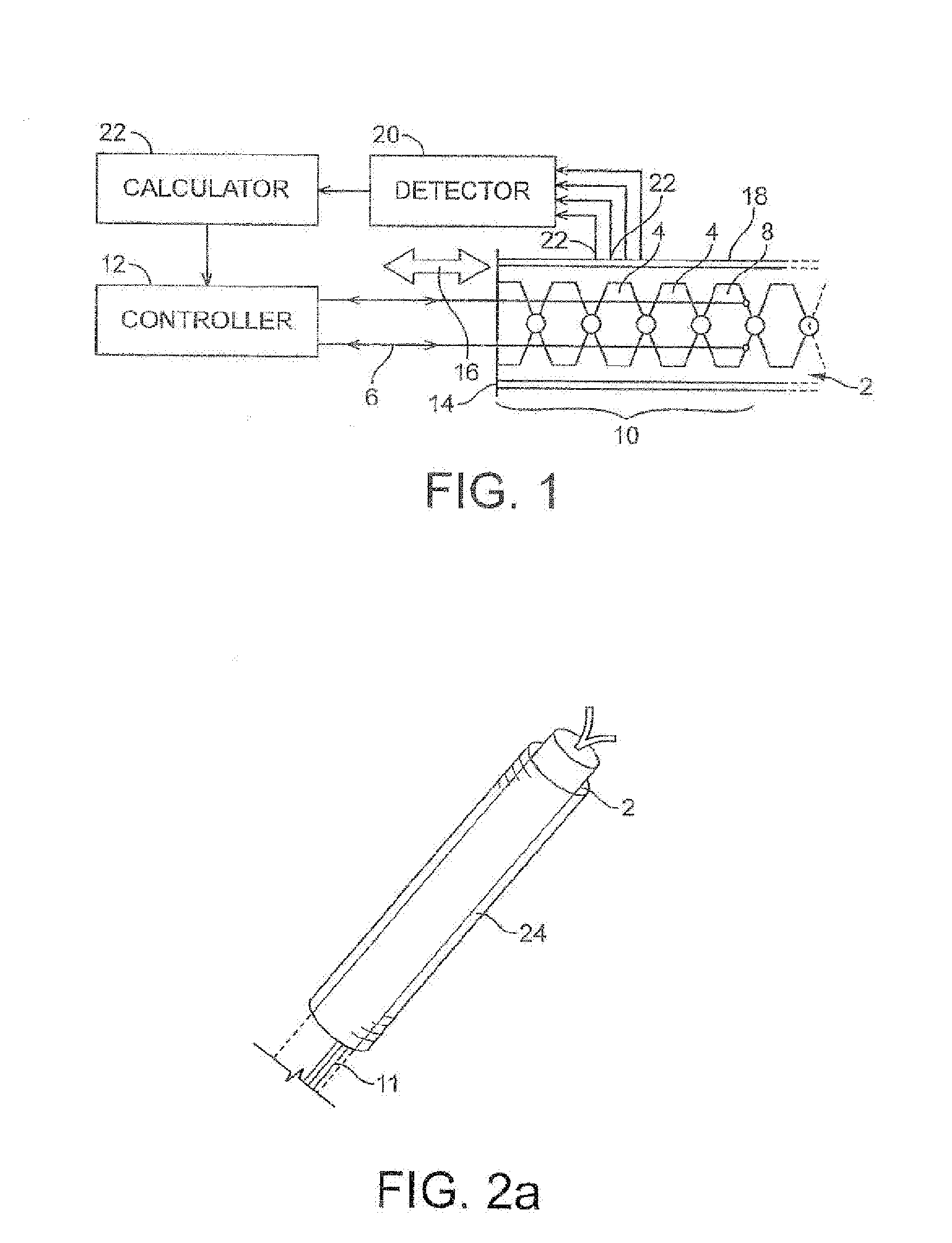
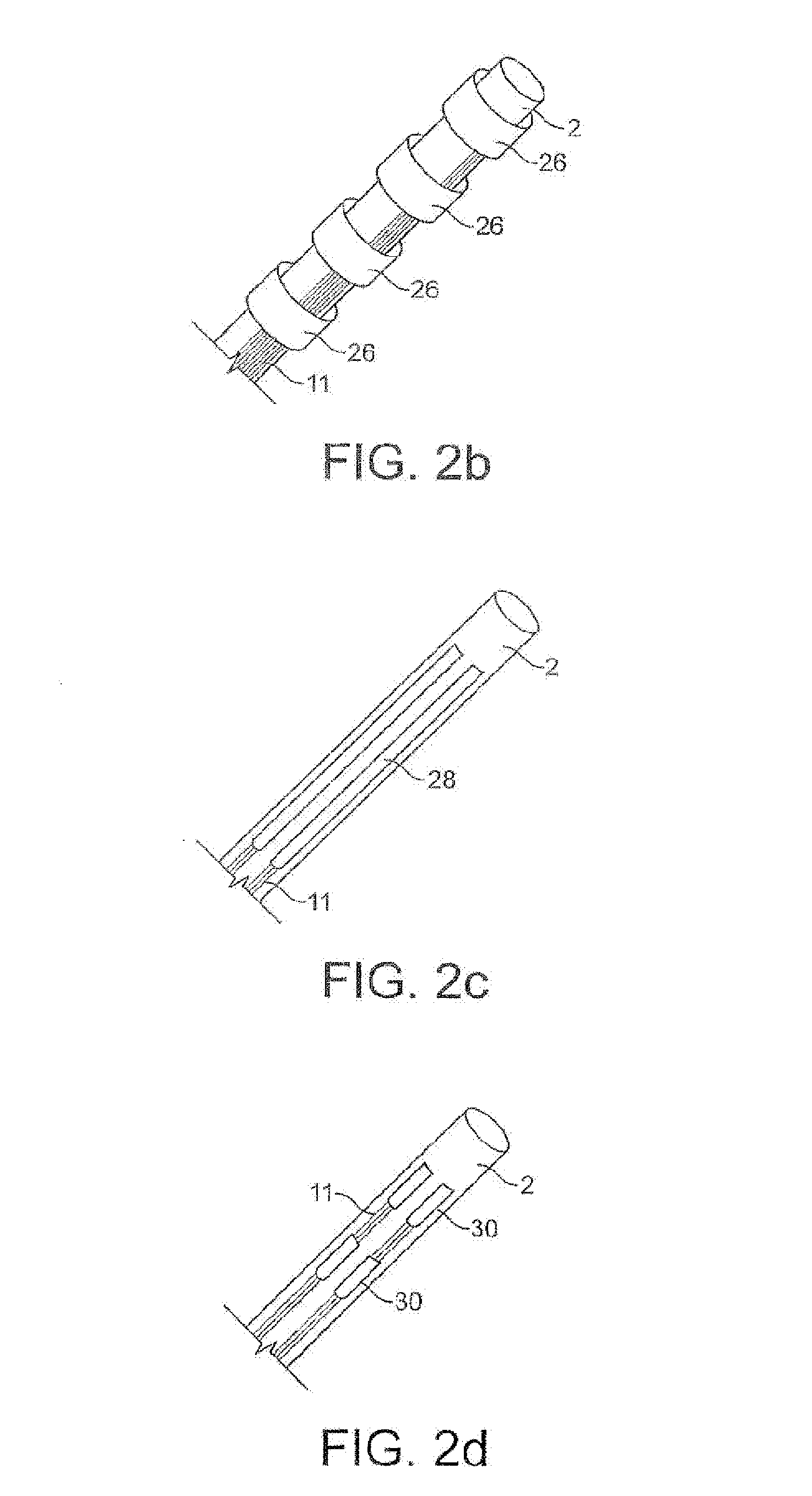
[0052]FIGS. 2A to 2D show various embodiments of the sensorised skin....


PUM


Abstract

A robotic arm of the “top following” type, which can advance into an environment is covered is covered by a sensorised skin. The arm can thus detect a parameter of the environment, and the shape can be adjusted accordingly.

Description

CROSS-REFERENCE TO RELATED APPLICATIONS[0001]The present application is a continuation of pending International patent application PCT / GB2007 / 004645 filed on Dec. 5, 2007 which designates the United States and claims priority from United Kingdom patent application 0624242.4 filed on Dec. 5, 2006, the content of which is incorporated herein by reference.FIELD OF THE INVENTION[0002]This invention relates to robotic arms, and in particular to robotic arms having ‘tip following’ capability.BACKGROUND OF THE INVENTION[0003]In the field of robotics there has been considerable development of robotic arms having a tip following capability; that is to say, the arm is capable of advancing longitudinally of itself in a snakelike manner. Such arms can carry a workload or tool and can be used for inspection of equipment with restricted access, such as the internal parts of a jet engine.[0004]Tip-following devices in general are used extensively in the medical field in the form of endoscopes and ...

Claims


Application Information

Patent Timeline
IPC IPC(8): G05B15/00
CPCA61B1/0053A61B1/0055A61B1/24B25J18/06A61B5/01A61B5/036B25J13/089A61B1/313
Inventor BUCKINGHAM, ROBERT OLIVERGRAHAM, ANDREW CRISPIN
Owner OLIVER CRISPIN ROBOTICS
Why Eureka
Try Eureka