

Membrane coating for a water pressurization Bladder
a membrane coating and water pressure technology, applied in the field of pressure vessels, can solve the problems of wear on the membrane material, increased work, and increased anomalous deformation of the membrane itself, and achieve the effects of reducing the air prolonging the life of the membrane, and reducing the permeability of the membrane material
Inactive Publication Date: 2010-01-07
MARTINELLO ERMANNO +1
View PDF8 Cites 12 Cited by
- Summary
- Abstract
- Description
- Claims
- Application Information
AI Technical Summary
Benefits of technology
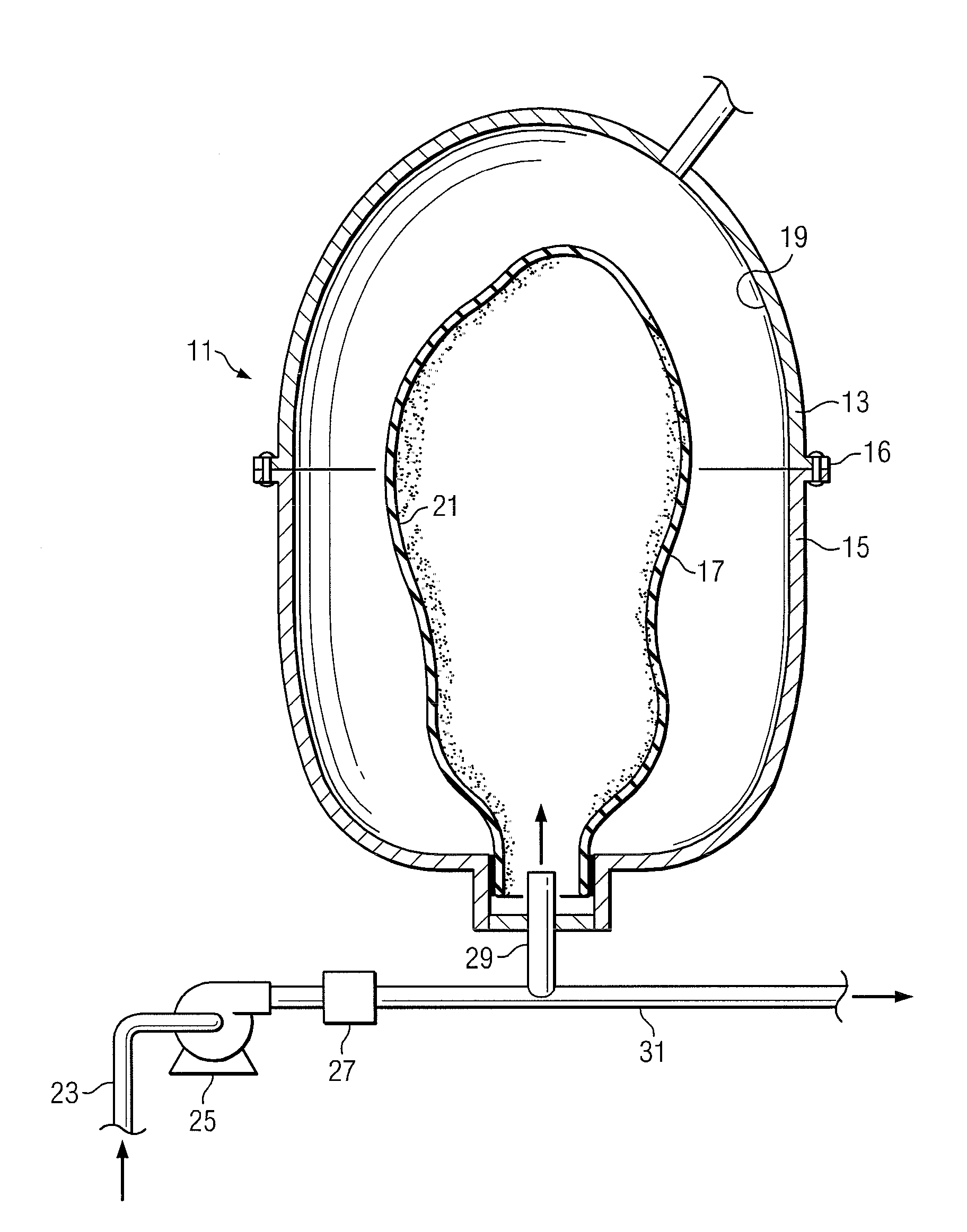
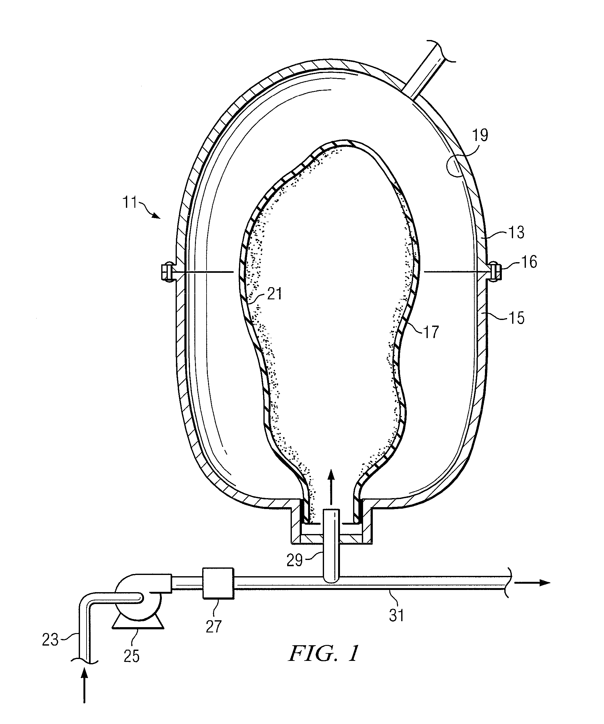
[0013]The water pressurization system of the invention includes an expansion tank which is formed of metal and which has an internal membrane which divides the tank interior into a water chamber and a compressed air chamber. A source of water is supplied to the water side of the tank and a source of compressed air is used to pressurize the opposite side of the tank. The membrane which is used to separate the two chambers of the tank is a specially manufactured membrane which has a special coating which reduces the permeability of the material of the membrane to air. By reducing the air permeability of the membrane, the life of the membrane is extended.
Problems solved by technology
As will be apparent from the discussion which follows, the rubber membrane works in abrasion against the metal of the tank interior and this action entails a wear on the material of the membrane over time.
A small part of the air which is used to pre-charge the tank passes through the rubber of the membrane into the water, thus causing a higher amount of work, a greater abrasion, and greater anomalous deformations of the membrane itself as the level in the hydraulic circuit fluctuates.
Method used
View moreImage
Smart ImageViewing Examples

Examples
example i
[0050]A bare EPDM rubber membrane was placed in the test chamber, kept at 15° C., and with nitrogen pressurized at 2 bar. After 7 days of exposure, the chamber lost 0.8% of its charge.
example ii
[0051]An EPDM rubber membrane coated with HYPALON 48 (chlorosulfonated polyethylene 43% chlorine and 1.1% sulfur available from Dupont de nemours) was placed in the chamber at 15° C., 2 bars of nitrogen, and after 7 days of exposure, lost 0.42% of its charge. This represents a rate of loss of charge 1.9 times better than no coating.
example iii
[0052]A bare SBR rubber membrane at 15° C., with nitrogen pressurized at 2 bar, after 7 days of exposure lost 1.2% of its charge.
Login to View More PUM
| Property | Measurement | Unit |
|---|---|---|
| thickness | aaaaa | aaaaa |
| temperature | aaaaa | aaaaa |
| Density | aaaaa | aaaaa |
Abstract
A water pressurization system is shown having a metal tank with a tank interior which is divided into first and second fluid chambers by a flexible membrane. One side of the tank interior is pressurized by compressed air. The membrane has a special coating applied thereto which decreases the natural permeability of the rubber material which is used to form the membrane. By decreasing the permeability of the membrane material, wear and tear on the membrane is decreased. The possibility of deloading the tank interior of pressurized gas due to the membrane permeability is also lessened.
Description
CROSS-REFERENCE TO RELATED APPLICATIONS[0001]The present application claims priority from the earlier filed provisional application, Ser. No. 61 / 078,657, filed Jul. 7, 2008, entitled “Water Pressurization System.BACKGROUND OF THE INVENTION[0002]1. Field of the Invention[0003]The present invention relates generally to pressure vessels of the type used in water pressurization systems and, more particularly, to such pressure tanks which include an elastomeric flexible membrane separating the interior of the tank into a compressible gas containing chamber and a liquid containing chamber.[0004]2. Description of the Prior Art[0005]Pressure control tanks are well known in the prior art and have been used in water supply systems, hot water heating systems and other types of water systems for many years. Generally, the tanks in such systems provide a needed quantity of pressurized water to the system upon demand, as in supplying drinking water for residential applications in potable water di...
Claims
Login to View More Application Information
Patent Timeline
 Patent Type & AuthorityApplications(United States)
IPC IPC(8): B01D71/24B05D3/10B32B25/04B32B9/04B32B27/00B32B27/36B32B27/30B32B27/40
CPCE03B7/07F15B1/165F15B2201/205Y10T428/265F24D3/1008F24D3/1016Y10T428/264F15B2201/3152Y10T428/31504Y10T428/31551Y10T428/31569Y10T428/31826
InventorMARTINELLO, ERMANNOWEIH, MARK
OwnerMARTINELLO ERMANNO