Apparatuses and methods using measurement of a flare generated in an optical system

Inactive Publication Date: 2010-01-07
CANON KK
View PDF3 Cites 5 Cited by
  • Summary
  • Abstract
  • Description
  • Claims
  • Application Information

AI Technical Summary

Benefits of technology

[0013]The present invention provides a techni

Problems solved by technology

Along with this trend, degradation in line width uniformity attributed to a flare generated in the projection optical system, which falls within the conventional tolerance, may become an issue.
The flare means herein stray light which adversely affects reticle pattern imaging.
Unfortunately, to measure flares generated unde

Method used


Image

  • Apparatuses and methods using measurement of a flare generated in an optical system
  • Apparatuses and methods using measurement of a flare generated in an optical system
  • Apparatuses and methods using measurement of a flare generated in an optical system

Examples


first embodiment

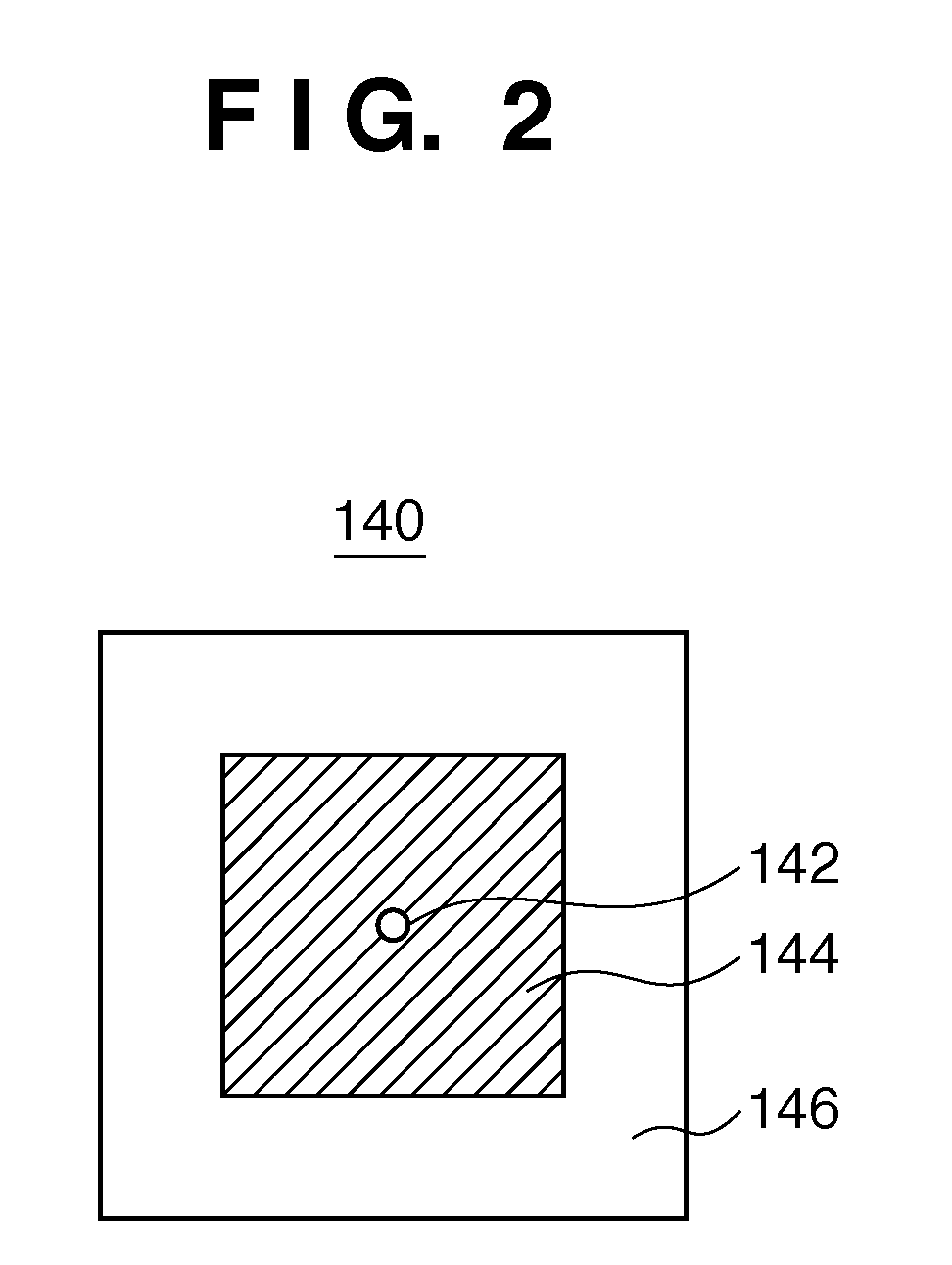
[0037]As will be explained in the first embodiment, the measurement surface is not limited to the pupil plane, and a flare can be obtained using a pupil function determined from the wavefront aberration and pupil transmittance distribution on an arbitrary measurement surface.

second embodiment

[0038]As will be explained in the second embodiment, a flare can be obtained using the wavefront aberrations on a plurality of measurement surfaces.

third embodiment

[0039]As will be explained in the third embodiment, a flare can be obtained by measuring the wavefront aberrations a plurality of times while changing the phase difference between a 0th-order light component and ±1st-order light components by a known amount, and using the plurality of measured wavefront aberrations.

[0040]Various embodiments of the present invention will be described below with reference to the accompanying drawings. Note that the same reference numerals denote the same members throughout the drawings, and a repetitive description thereof will not be given.

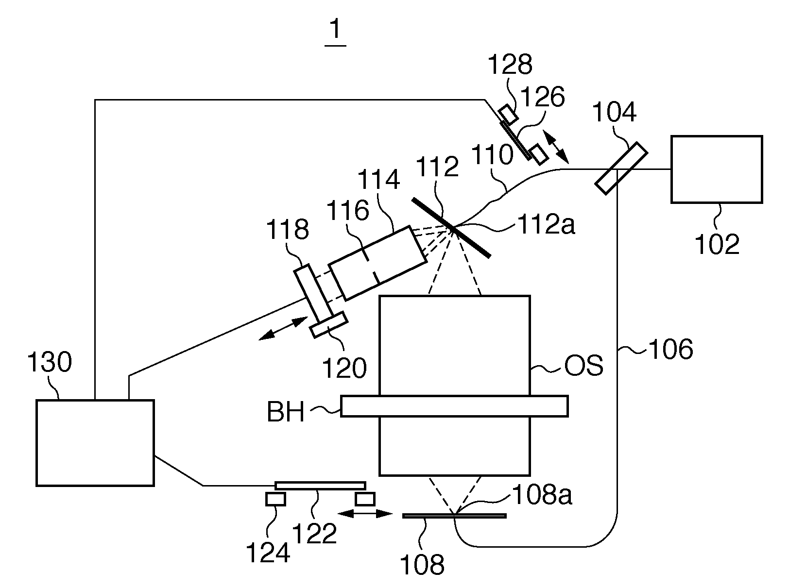
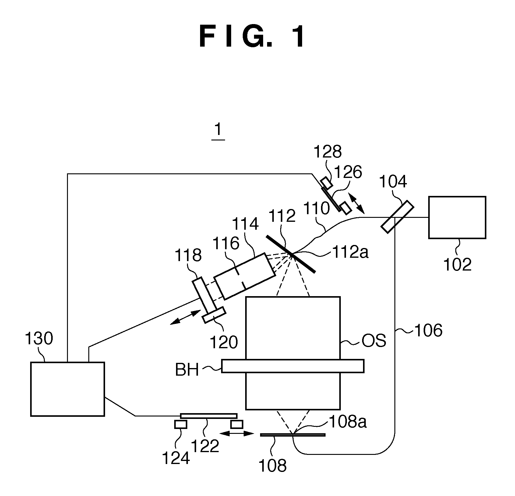
[0041]In a first embodiment, the wavefront aberration and pupil transmittance distribution on an arbitrary measurement surface (observation surface) of an optical system to be measured such as a projection optical system, are measured, and a flare generated in the optical system to be measured is obtained from the measured wavefront aberration and pupil transmittance distribution.

[0042]The wavefront aberration and ...


PUM


Abstract

The present invention provides a method including measuring a wavefront aberration of the optical system to be measured on a measurement surface, measuring a pupil transmittance distribution of the optical system determining a pupil function of the optical system based on the wavefront aberration and the pupil transmittance distribution, and performing imaging computation using the pupil function to obtain a light intensity distribution formed on an image plane of the optical system, and calculating a flare, generated in the optical system, from the light intensity distribution.

Description

BACKGROUND OF THE INVENTION[0001]1. Field of the Invention[0002]The present invention relates to an optical system and more particularly to the measuring of a flare in an optical system.[0003]2. Description of the Related Art[0004]A projection exposure apparatus has been conventionally employed to fabricate a micropatterned semiconductor device using photolithography. The projection exposure apparatus projects and transfers a circuit pattern formed on a reticle (mask) onto a substrate such as a wafer by a projection optical system. In recent years, as micropatterning of semiconductor devices advances, a demand for the line width uniformity of a pattern transferred onto a wafer is becoming stricter. Along with this trend, degradation in line width uniformity attributed to a flare generated in the projection optical system, which falls within the conventional tolerance, may become an issue. The flare means herein stray light which adversely affects reticle pattern imaging.[0005]Flares...

Claims


Application Information

Patent Timeline
IPC IPC(8): G01B9/02G01B9/00
CPCG03F7/705G03F7/70525G03F7/70941G03F7/7085G03F7/706G03F7/70883
Inventor AIZAWA, MICHIKOAOKI, EIJIKAKUCHI, OSAMUKURAMOTO, YOSHIYUKI
Owner CANON KK
Why Eureka
Try Eureka