Lighting system, method of lighting, and scanning optical microscope

a scanning optical microscope and light source technology, applied in the field of scanning optical microscopes, lighting systems, lighting and heating apparatuses, instruments, etc., can solve the problems of inability to carry out image dissection of structures smaller than the diffraction limit, limited resolution capacity of image pickup optical systems,

Inactive Publication Date: 2010-01-07
OLYMPUS CORP
View PDF2 Cites 30 Cited by
  • Summary
  • Abstract
  • Description
  • Claims
  • Application Information

AI Technical Summary

Problems solved by technology

Particularly, in a field of microscopes and optical recording, an optical system with almost no aberration has been realized, and a resolution capacity as an image pickup optical system has been restricted mainly by a diffraction limit of visible light.
However, a condition for the perfect imaging being extremely strict, and since a material having a predetermined refractive index gradient in addition to exhibiting negative refraction is necessary, it is not realistic.
Moreover, a structure smaller than the diffraction limit cannot carry out image dissection by an optical system.
Here, it is not possible to make the numerical aperture NA larger than a refractive index of a medium in which, an object plane is disposed.
Moreover, it has been known that for many metals, a real part of permittivity with respect to visible light becomes negative.
However, for generating arbitrarily some sort of optical image having the high-frequency component by using a negative refraction lens, or for detecting the high-frequency component from an optical image generated from an object etc. by a negative refraction lens, there are following issues related to a method of lighting and a method of detection.
Moreover, even when the uniformly magnified image is supposedly magnified by an ordinary magnifying optical system, the evanescent waves are not transmitted to the magnified image.
Consequently, the high-frequency component is lost, and it is not possible to detect the high-frequency component from the magnified image.
Such type of problem exists similarly when an attempt is made to generate arbitrarily on an object, some sort of an optical image having the desired high-frequency component by using the negative refraction lens.
However, manufacturing of such extremely small detector and light source is not easy.
This technological degree of difficulty is extremely high.

Method used


Image

  • Lighting system, method of lighting, and scanning optical microscope
  • Lighting system, method of lighting, and scanning optical microscope
  • Lighting system, method of lighting, and scanning optical microscope

Examples


first embodiment

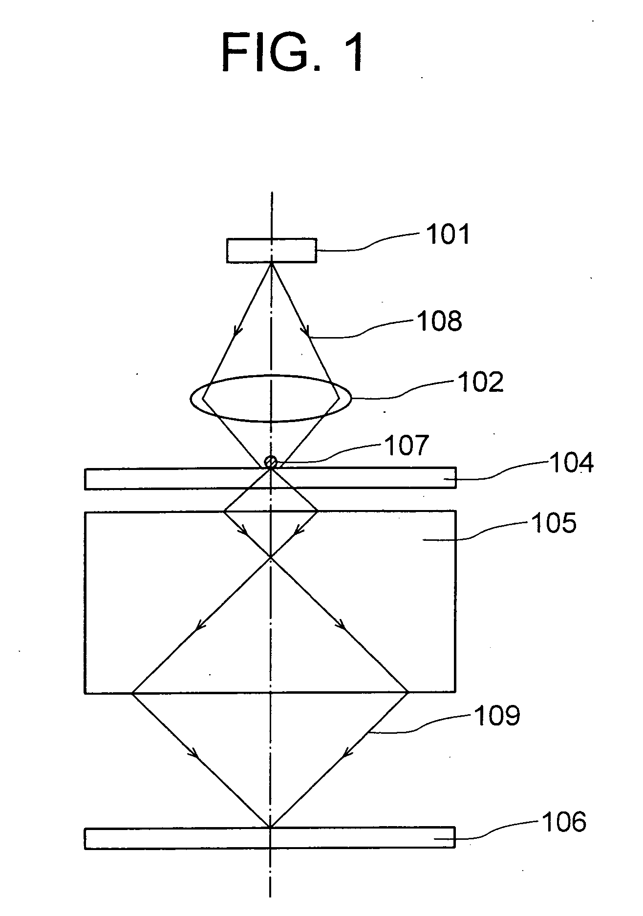
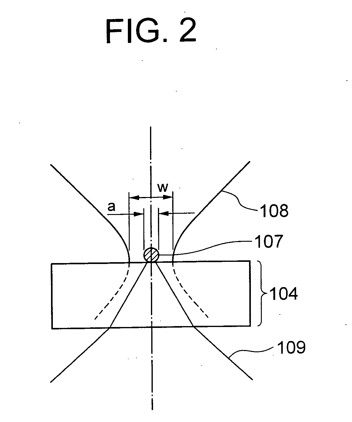
[0074]FIG. 1 shows a structure of a lighting system according to a first embodiment. A light source 101 is an illuminating light source such as a halogen lamp, a light emitting diode (LED), a super luminescent diode (SLD), and a laser oscillator, and since the laser light has a superior spatial coherence, it is preferable from a point of forming a beam spot having a higher energy density. A light emitter excitation light 108 of a wavelength λ1 which the light source 101 has emitted, is focused on a light emitter 107 by a collective lens 102. The light emitter 107 is a fine particle made of a florescent substance or a phosphorescence substance which emits light of a wavelength longer than excitation light by irradiating the excitation light, and a size of the light emitter 107 is smaller than a wavelength of the fluorescent light or the phosphorescent light emitted by the light emitter 107.

[0075]As the light emitter 107, it is possible to use a so-called fluorescent bead in which, pl...

second embodiment

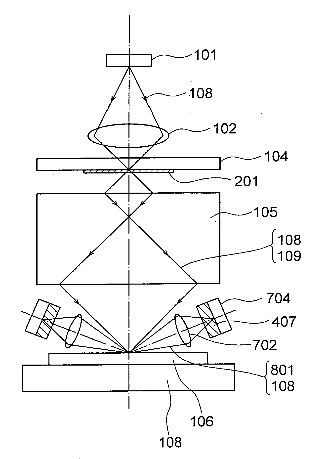
[0080]Next, a second embodiment of the present invention will be described below. Same reference numerals are assigned to components which are same as in the first embodiment, and repeated description is omitted. FIG. 3 shows a structure of a lighting unit according to the second embodiment. A structure of the second embodiment is basically same as the structure of the first embodiment, and differs at a point of having a light emitting layer 201. The light emitting layer 201 is a film formed on the substrate 104, in which, a plurality of light emitters 107 is disposed by being dispersed spatially in a transparent substance.

[0081]FIG. 4 is a diagram in which, the light emitting layer 201 and the substrate 104 in FIG. 3 are enlarged. The light emitting layer 201 is formed by making the plurality of light emitters 107 to be dispersed in a film made of a transparent material.

[0082]The light emitter 107 being extremely small, when there is only one light emitter held on the substrate 104...

third embodiment

[0085]Next, a third embodiment of the present invention will be described below. Same reference numerals are assigned to components which are same as in the embodiments described above, and the repeated description is omitted. In the first embodiment (FIG. 1) and the second embodiment (FIG. 3), since the fluorescent light emitted by the light emitter 107 passes through the substrate 104, there is a possibility that the beam spot formed on the object 106 is blurred due to scattering and absorption of the fluorescent light inside the substrate, or due to the scattering and reflection at a surface of the substrate. Therefore, as shown in FIG. 6, when the light emitter 107 is held at a rear side of the substrate 104 (as seen from a light source side), it is possible to avoid an occurrence of the blurring. Moreover, for achieving the same effect, as shown in FIG. 7, a structure in which, the negative refraction lens 105 holds the light emitter 107, without using the substrate 104 is also...


PUM


Abstract

Light emitter excitation light (108) of a wavelength λ1 emitted by a light source (101) is collected on a light emitter (107) by a collective lens (102). The light emitter (107) is held on a substrate (104), and emits fluorescent light of a wavelength λ2 when the light emitter excitation light (108) of the wavelength λ1 is irradiated. A diameter of the light emitter (107) being formed to be smaller than the wavelength λ2, this fluorescent light includes evanescent waves, and advances through the substrate (104) as an object illuminating light (109) having the light emitter (107) as a point light source. A negative refraction lens (105) is disposed such that an image of the light emitter (107) is formed on a surface of an object 106, and accordingly, not only a propagating-light component included but also a evanescent-wave component in the object illuminating light (109) is also collected simultaneously, and a minute beam spot of a size almost same as of the light emitter (107) is formed on the surface of the object (106).

Description

TECHNICAL FIELD[0001]The present invention relates to a lighting system, a method of lighting which can be used in an optical image detector such as a microscope, a camera, and an endoscope, an optical information writing and reading apparatus such as a pickup for an optical disc, and a lithographic apparatus such as a stepper, and a scanning optical microscope.BACKGROUND ART[0002]In recent years, a resolution capacity of an image detecting apparatus in which, an image pickup optical system such as a microscope, a camera, and an endoscope is used has improved. Particularly, in a field of microscopes and optical recording, an optical system with almost no aberration has been realized, and a resolution capacity as an image pickup optical system has been restricted mainly by a diffraction limit of visible light. Whereas, as it has been disclosed in the following non-patent literatures, an optical material which takes a negative value of a refractive index (hereinafter, ‘negative refrac...

Claims


Application Information

Patent Timeline
Patent Type & Authority Applications(United States)
IPC IPC(8): G02B21/06F21V3/04G02B27/20
CPCB82Y20/00G02B1/007G02B21/16G02B21/082G02B21/002
Inventor FUKUYAMA, HIROYA
Owner OLYMPUS CORP
Why Eureka
Try Eureka