Microbial fuel cell stack

a fuel cell and microorganism technology, applied in the field of microorganism fuel cell stacks, can solve the problems of difficult to prevail in stackable air-cathode single-chamber mfc, difficult to output the required voltage and current, and adopt an expensive proton-exchange membrane, etc., to achieve compact structure, increase the effect of voltage and current of the mfc stack, and occupie less spa

Active Publication Date: 2010-01-07
GUANGDONG INST OF ECO ENVIRONMENT & SOIL SCI
View PDF7 Cites 33 Cited by
  • Summary
  • Abstract
  • Description
  • Claims
  • Application Information

AI Technical Summary

Benefits of technology

[0021]The present invention is characterized in that the pipe wrapped by a filmed cathode is used as the anode chamber, and that oxygen is supplied to the cathode via passive aeration, and that wastewater is fed into the cells via a joint feeding port, continuously and sequentially processed by many cells to achieve a discharge standard, and then drained out from a joint discharging port. The present invention can effectively increase the voltage and current of an MFC stack. The present invention needn't consume power to actively supply oxygen. Further, the present invention has a compact structure and occupies less space. Further, the spiral-type structure enables the expansion of the present invention. Furthermore, the present invention is inexpensive and easy to maintain. Moreover, the present invention has high output power density and superior capability of reduce COD. Therefore, the present invention should be very useful in industry.

Problems solved by technology

However, a single microbial fuel cell is hard to output the required voltage and current at present.
However, the prior-art patent adopts an expensive proton-exchange membrane.
Therefore, the stackable air-cathode single-chamber MFC is hard to prevail.
The proton exchange membrane-based MFC is impractical and short of utility.2. Oxygen needs continuously supplying to the cathode for oxygen reduction reaction.
The oxygen supply process consumes more energy than the energy generated.
Therefore, the conventional MFC is unable to sustain the operation by itself.
Although a single cell of this type can work, the cells of this type are hard to stack for amplifying output.3. The structure and operation of the conventional MFCs are unfavorable for amplifying output.

Method used


Image

  • Microbial fuel cell stack
  • Microbial fuel cell stack
  • Microbial fuel cell stack

Examples


embodiment i

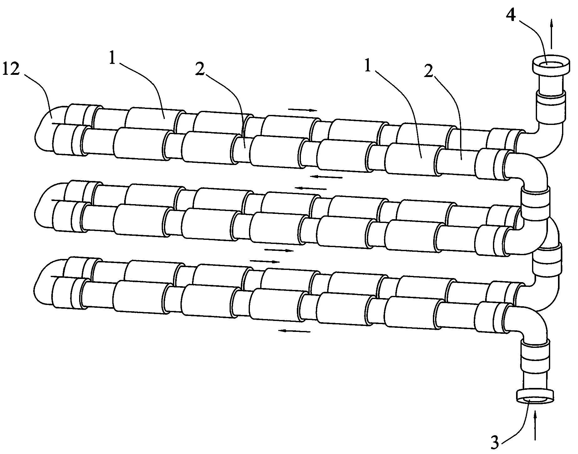
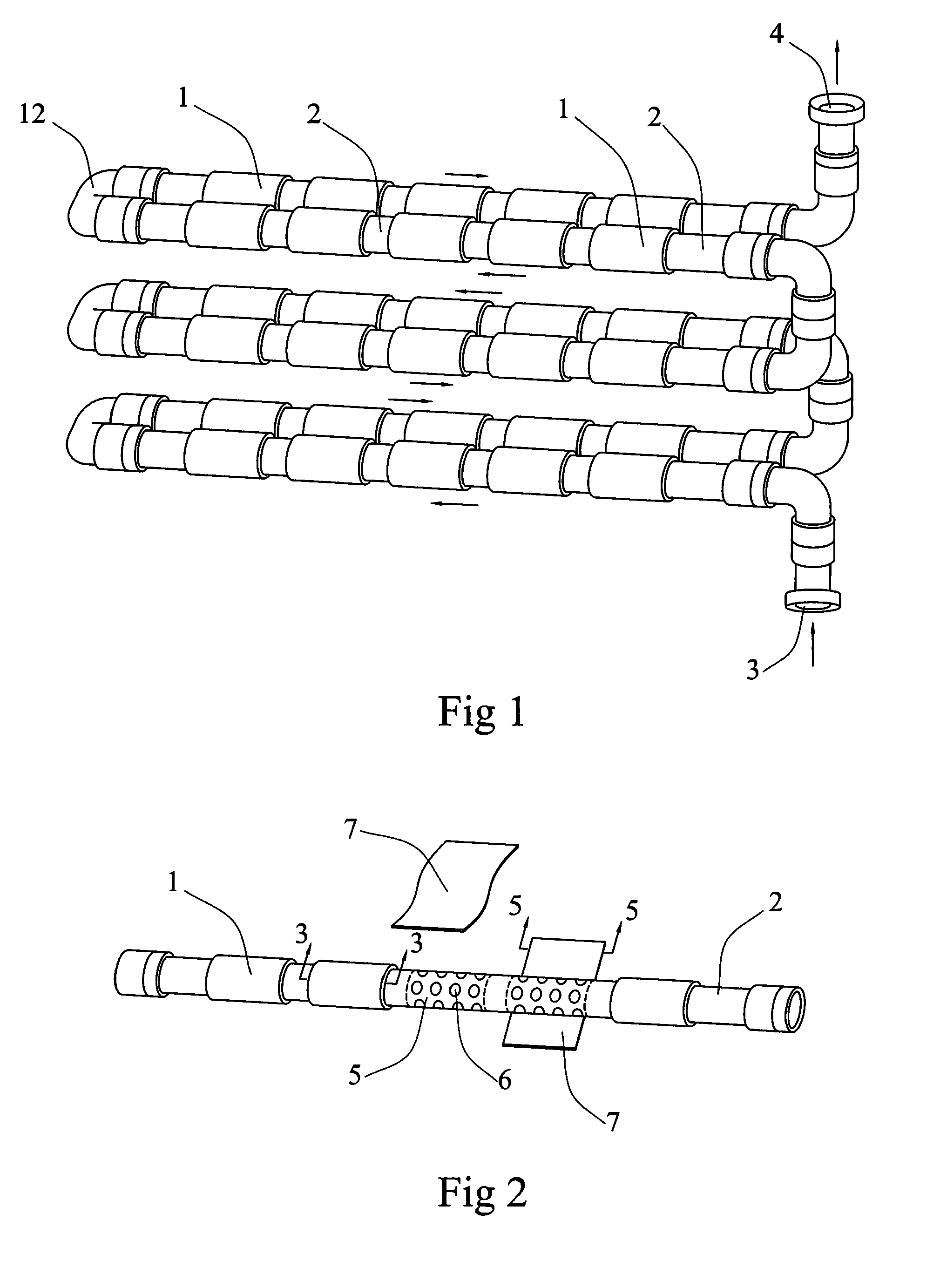
[0031]As shown in FIG. 1 and FIG. 2. A 5 cm-diameter PVC (polyvinylchloride) pipe is fabricated into frames 5 having a length of 13 cm segment by segment. Each PVC pipe is fabricated into five microbial fuel cells 1. Because of the continuity of the pipes 2, the anode chambers of the five microbial fuel cells 1 connect head to tail sequentially and interconnect each other. In the embodiment shown in FIG. 1, two PVC pipes are arranged in parallel to form one layer of the MFC stack. In FIG. 1, six PVC pipes are interconnected by elbows 12 to form three layers. The ends of the first PVC pipe and the last PVC pipe respectively have a feeding port 3 and a discharging port 4. Thus, the thirty pieces of microbial fuel cells 1 form a three-layer MFC stack. Wastewater enters the MFC stack from the feeding port 3, flows through all the microbial fuel cells 1 and then drains out from the discharging port 4. In FIG. 1, the arrows indicate the flow direction of the wastewater.

[0032]As shown in F...

embodiment ii

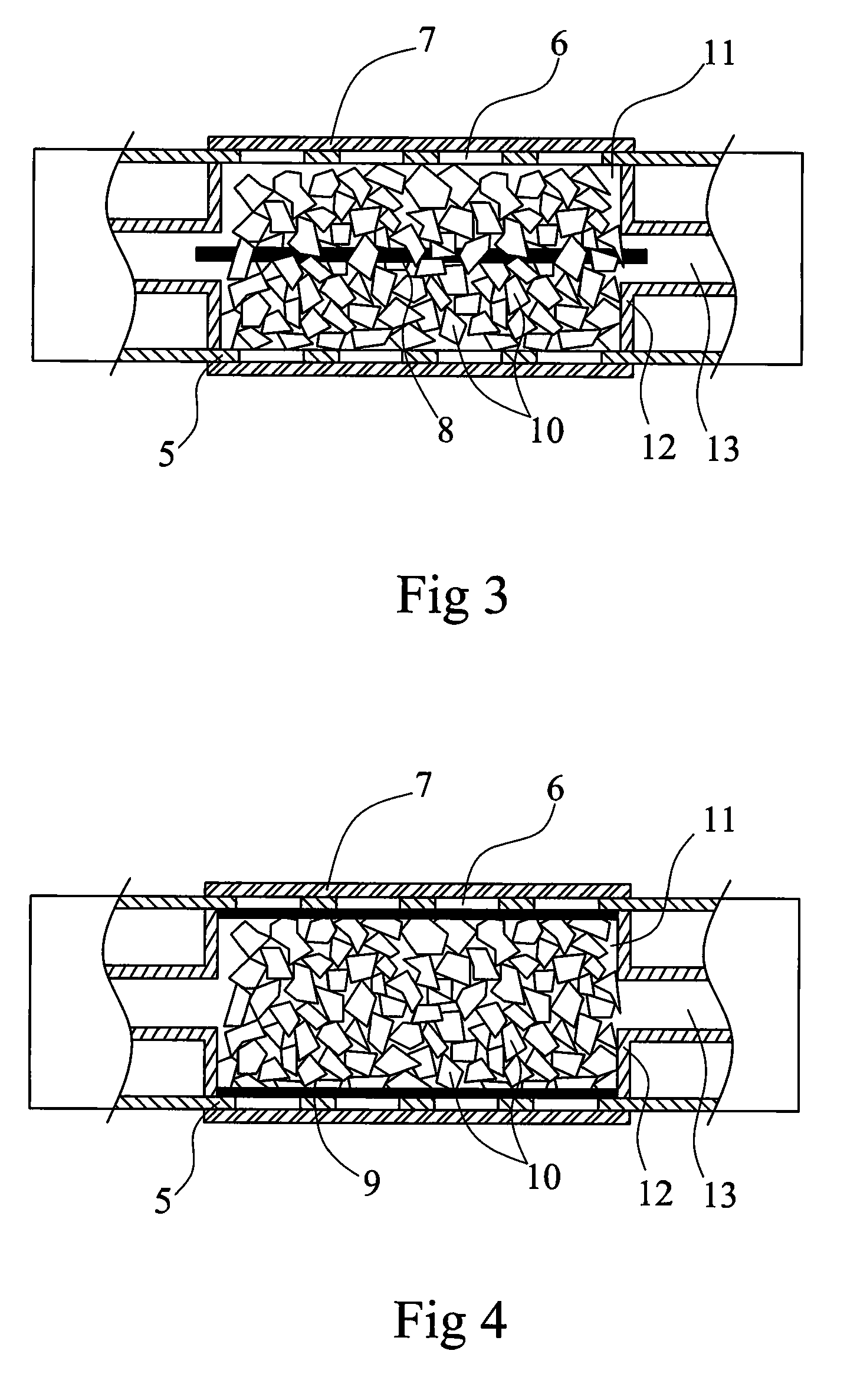
[0035]Embodiment II is different from Embodiment I in the structures of the anode chamber and the cathode. Refer to FIG. 4. A PVC pipe with 23 cm in length and 5 cm in diameter is used as the frame 5. On the frame 5 is perforated holes 6 with a diameter of 1 cm and a hole density of 1000 holes / m2. A 13 cm long, 14.5 cm wide and 0.5 cm thick graphite felt 9 is rolled up to have a cylinder form. The cylindrical graphite felt 9 is placed in the pipe and filled up with graphite grains 10. A titanium wire connects with the graphite felt 9 to function as the conductive wire of the anode. The graphite felt 9 of one MFC is connected to the cathode 7 of next MFC with the titanium wire sequentially to assemble thirty pieces of MFCs into a cascade MFC stack.

[0036]Refer to FIG. 6 for the structure of a cathode. In Embodiment II, the cathode 7 is a fabric-based cathode and includes a waterproof air-permeable layer 75, a fabric-based layer 74 and a conductive catalytic layer 73. A piece of 14.5 c...

embodiment iii

[0039]Embodiment III is different from Embodiment II in the material of the cathode. A piece of 29 cm long, 35 cm wide and 0.5 mm thick denim is used as the fabric-based layer 74. The cathode 7 is fabricated according to the following steps: dissolving 3.0 g PTFE in 40.0 ml N-methyl-2-pyrrolidone, uniformly stirring the mixture, evenly applying the mixture onto one surface of the denim, air-drying the coated denim for 10 hours, and baking the air-dried drying coated denim at a temperature of 70° C. for 2 hours, whereby the coated denim has a PTPE density of 3.0 mg / cm2; ultrasonically dispersing the mixture of 1.0 g CoTMPP (the oxygen reduction catalytic) and 25.0 g graphite-based conductive paint for 15 minutes into a slurry; evenly applying the slurry on the other surface of the denim, air-drying the double-coated denim for 10 hours, and baking air-dried double-coated denim at a temperature of 70° C. for 2 hours, whereby the double-coated denim has a CoTMPP density of 1.0 mg / cm2.


PUM

PropertyMeasurementUnit
diameteraaaaaaaaaa
lengthaaaaaaaaaa
diameteraaaaaaaaaa

Abstract

The present invention discloses a microbial fuel cell stack, which comprises a plurality of microbial fuel cells and is characterized in that the microbial fuel cell includes a perforated frame, a cathode and an anode, and that the cathode wraps the perforated frame to form an anode chamber, and that the anode is arranged inside the anode chamber. Wires are respectively extended from the cathode and the anode. The microbial fuel cells are connected head to tail sequentially via pipes, and thus the anode chambers thereof interconnect each other. The first microbial fuel cell of the cell stack has a feeding port, and the last one has a discharging port.

Description

FIELD OF THE INVENTION[0001]The present invention relates to a microbial fuel cell technology, particularly to a microbial fuel cell stack.BACKGROUND OF THE INVENTION[0002]MFC (Microbial Fuel Cell) converts chemical energy of organic compounds into electric energy and thus has the functions of power generation and waste treatment simultaneously. Many types of waste can be used as the fuel of MFC, including domestic wastewater, high-density organic wastewater, and human / animal excrement. Therefore, MFC can generate electric energy and effectively dispose organic waste.[0003]Below is the principle of MFC: Organic materials are oxidized by microbes in an anaerobic anode chamber; the microbes capture electrons and transfer electrons to the anode; electrons flow through the external circuit and reach the cathode; protons pass through the exchange membrane to reach the cathode and react with oxygen there to form water; thus is formed a loop for current. China application No. 200710144804....

Claims


Application Information

Patent Timeline
Patent Type & Authority Applications(United States)
IPC IPC(8): H01M8/16
CPCY02E60/527H01M8/16Y02E60/50
Inventor ZHOU, SHUNGUI
Owner GUANGDONG INST OF ECO ENVIRONMENT & SOIL SCI
Why Eureka
Try Eureka