Interventional device for RF ablation for use in RF fields

a technology for rf ablation and interventional devices, which is applied in the field of interventional devices for rf ablation for use in rf fields, can solve the problems of patient injury, catheter tracking and tissue ablation cannot be conducted at the same time,

Active Publication Date: 2010-01-07
KONINKLIJKE PHILIPS ELECTRONICS NV
View PDF4 Cites 12 Cited by
  • Summary
  • Abstract
  • Description
  • Claims
  • Application Information

AI Technical Summary

Benefits of technology

[0015]The coupling elements according to the embodiments of claims 2 and 3 have the advantage that they can be realized in a comparatively simple manner for the relevant frequencies, so that an appropriate coupling and stray capacity is achieved.
[0016]The embodiment according to claim 4 has the advantage that the ablation catheter or probe can be tracked, guided and / or visualized (especially by means of MR signals which are detected by the MR / RF micro-coil) well defined and distinctively in the MR image generated by a MR imaging system.
[0017]The embodiments according to claims 5 and 6 have the advantage that only one transmission path or line or cable is necessary for feeding ablation power to the ablation catheter or probe, and for feeding the MR / RF signals which are detected and / or transmitted by the MR / RF micro coil between this coil and the MR / RF receiver and / or transmitter.
[0018]The embodiments according to claims 7 and 8 have the advantage that a compact interventional device for MR guided ablation is provided which can be used as a separate unit in different MR imaging systems and independently from a specific kind of such a system.

Problems solved by technology

It has revealed that a disadvantage of the ablation system as discloses in the U.S. Pat. No. 6,246,896 is that catheter tracking and tissue ablation cannot be conducted at the same time.
Furthermore, there is a considerable risk that due to RF transmission (B1 field) by the MR system during position measurement (as well as during the normal MR imaging), the ablation device and especially the cable or transmission path connecting the ablation device with the switch or another component of the MRI system is heated up unintentionally (and the adjacent body tissue of the patient as well) due to standing waves on the cable or transmission path, so that the patient can be hurt.

Method used


Image

  • Interventional device for RF ablation for use in RF fields
  • Interventional device for RF ablation for use in RF fields
  • Interventional device for RF ablation for use in RF fields

Examples


Embodiment Construction

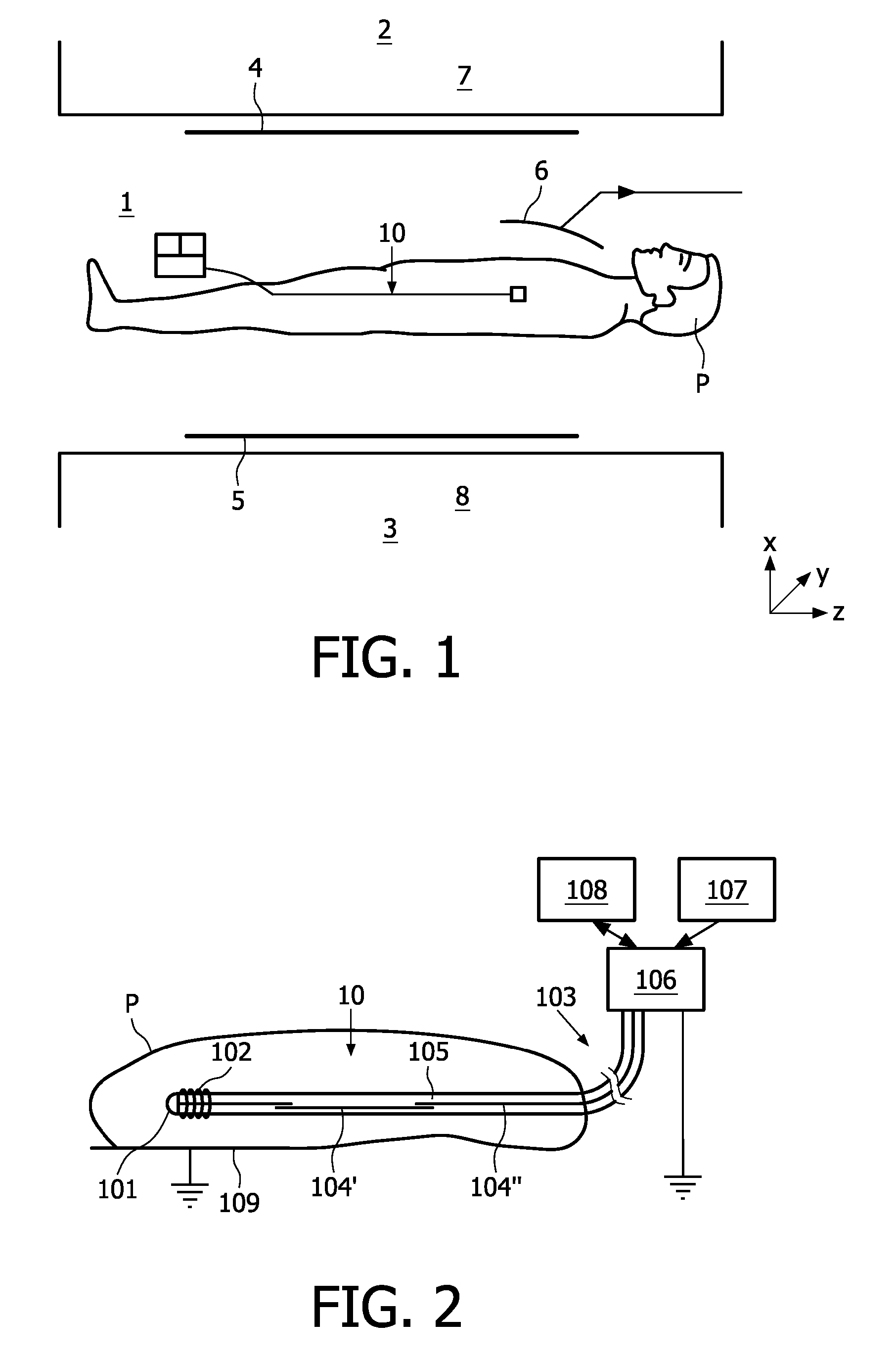
[0025]FIG. 1 shows substantial components of a MR imaging system, which are of essential importance for the generation of magnetic fields and RF pulses and for receiving MR relaxation signals in an examination zone 1. Above and underneath the examination zone 1 there are provided respective magnet systems 2, 3 which serve to generate an essentially uniform main magnetic field (B0 field for aligning the nuclear spins in the object to be examined) whose magnetic flux density (magnetic induction) may be in the order of magnitude of from some tenths of Tesla to some Tesla. The main magnetic field essentially extends through a patient P in a direction perpendicular to the longitudinal axis of the patient (that is, in the x direction).

[0026]Planar or at least approximately planar RF conductor structures (surface resonators) in the form of RF transmission coils 4 serve to generate RF pulses (B1 field) of the MR frequency whereby the nuclear spins are excited in the tissue to be examined, s...


PUM


Abstract

A interventional device for RF ablation for use in a RF electrical and/or magnetic field especially of a MR imaging system is disclosed, comprising an ablation catheter which is preferably trackable or can be guided or visualized in the image generated by the MR imaging system by means of a MR micro-coil (102), and which is provided with an ablation electrode (101). The interventional device further comprises a transmission path (103) with line segments (104′, 104″) and transformers (105) therebetween, for connecting the MR micro-coil (102) in a differential mode with a MR receiver (108) and for connecting a RF amplifier (107) in a common mode with the ablation electrode (101) for conveying RF ablation power.

Description

FIELD OF THE INVENTION[0001]The invention relates to an interventional device comprising an ablation catheter for RF ablation of body tissue, or a transdermal ablation probe (or needle), e.g. for tumor ablation in the liver, prostate or kidney, or generally for use in electrophysiologic (EP) interventions, and a connected transmission path, wherein the device is provided for use in a RF electrical and / or magnetic field especially of a MR imaging system and especially for visualizing the catheter or probe in a MR image. The invention further relates to a MR imaging system comprising such an interventional device.BACKGROUND OF THE INVENTION[0002]U.S. Pat. No. 6,246,896 discloses a MRI guided ablation system comprising a tracking coil which serves dual purposes. At first it provides NMR tracking data for the MRI system which is used to help a physician to guide the ablation device into a proper treatment position within the patient, and thereafter it is used by the ablation system to d...

Claims


Application Information

Patent Timeline
Patent Type & Authority Applications(United States)
IPC IPC(8): A61B5/055A61B18/18
CPCA61B5/042A61B5/06A61B18/1492A61B2019/5236A61B2019/5251G01R33/3628G01R33/287G01R33/288G01R33/34053G01R33/34084A61B2562/222A61B2090/374A61B2034/2051A61B5/283
Inventor WEISS, STEFFENGLEICH, BERNHARD
Owner KONINKLIJKE PHILIPS ELECTRONICS NV
Why Eureka
Try Eureka