Heat transfer cell for heat exchanger and assembly, and methods of fabricating the same

a heat exchanger and heat transfer cell technology, applied in indirect heat exchangers, lighting and heating apparatuses, laminated elements, etc., can solve the problems of increasing the burden of workers, reducing work efficiency, increasing fabrication costs, etc., to prevent downward sagging, improve heat exchange efficiency, and reduce the vortex and resistance of fluids

Inactive Publication Date: 2010-01-14
EURO - APEX
View PDF14 Cites 27 Cited by
  • Summary
  • Abstract
  • Description
  • Claims
  • Application Information

AI Technical Summary

Benefits of technology

[0061]According to the exemplary embodiments of the present invention, the cell body is configured so that a pair of heat transfer plates includes a pair of first flanges and a pair of second flanges, each of which has a height difference with respect to the quadrilateral heat transfer area and is bent in a direction perpendicular to the other pair of flanges, is joined so as to opposite to each other in a mirror image, thereby forming a first fluid passage and weld lines along the flanges contacting each other. Thereby, the cell body can minimize vortex and resistance of fluid at and in the inlet of a passage into and through which the fluid flows, so that it can increase a contact area between the fluid and its contact plate and stably maintain contact between the fluid and the heat transfer plate, thereby improving heat exchange efficiency.
[0062]Further, each heat transfer cell prevents downward sagging due to weight of the heat transfer plate when a heat transfer assembly is fabricated by stacking a plurality of heat transfer cells in multiple layers, so that it can prevent welding defects and reduce the number of whole constituent parts and the resulting fabricating costs.
[0063]In addition, an air space is additionally formed at the inlet into which the fluid having a relatively lower temperature flows, so that the moisture can be prevented from being generated by a sharp temperature difference when the heated plate exchanges heat with the fluid. Thereby, the corrosion caused by the moisture can be prevented, and a lifespan can be prolonged.

Problems solved by technology

For this reason, a process of individually welding the bars to an inlet and an outlet between the adjacent plates disposed in parallel requires a high precision of welding, which further increases the burden of a worker and reduces work efficiency.
Further, the number of constituent parts is increased to act as a main factor that increases fabrication costs.
When each plate made of metal is welded, the plate sags due to its own weight, which leads to a failure in welding.
Thus, this welding failure acts as a factor that reduces product reliability.
For this reason, a contact area between the plate as the heat transfer member and the fluid is reduced, and thus heat exchange efficiency is reduced.
The moisture acts as a main factor that corrodes the plate made of metal to reduce the lifespan of the product.

Method used


Image

  • Heat transfer cell for heat exchanger and assembly, and methods of fabricating the same
  • Heat transfer cell for heat exchanger and assembly, and methods of fabricating the same
  • Heat transfer cell for heat exchanger and assembly, and methods of fabricating the same

Examples


first embodiment

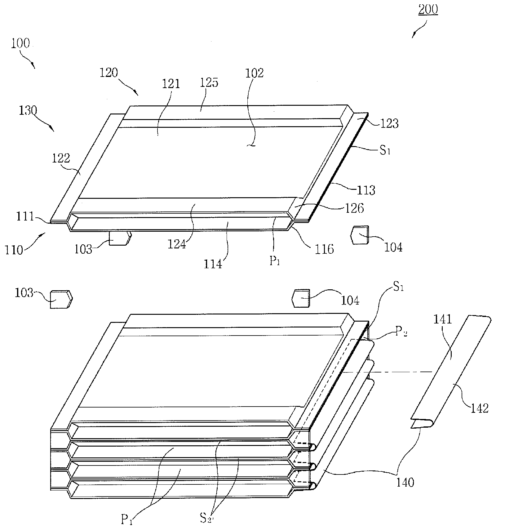
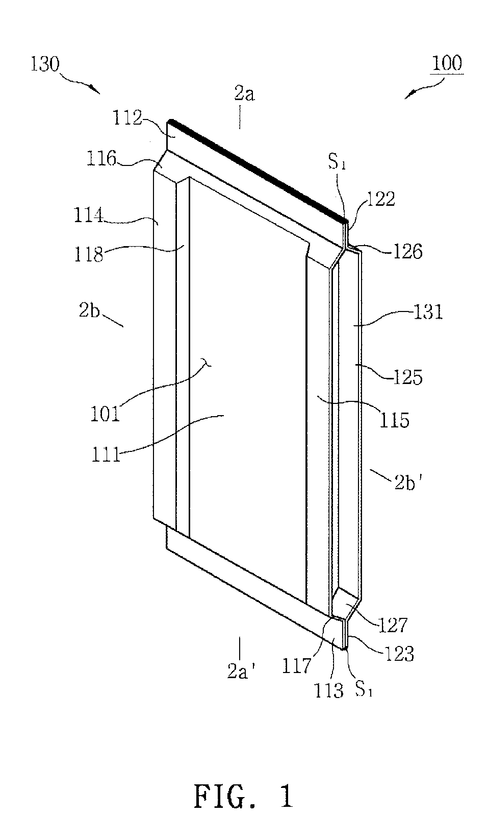
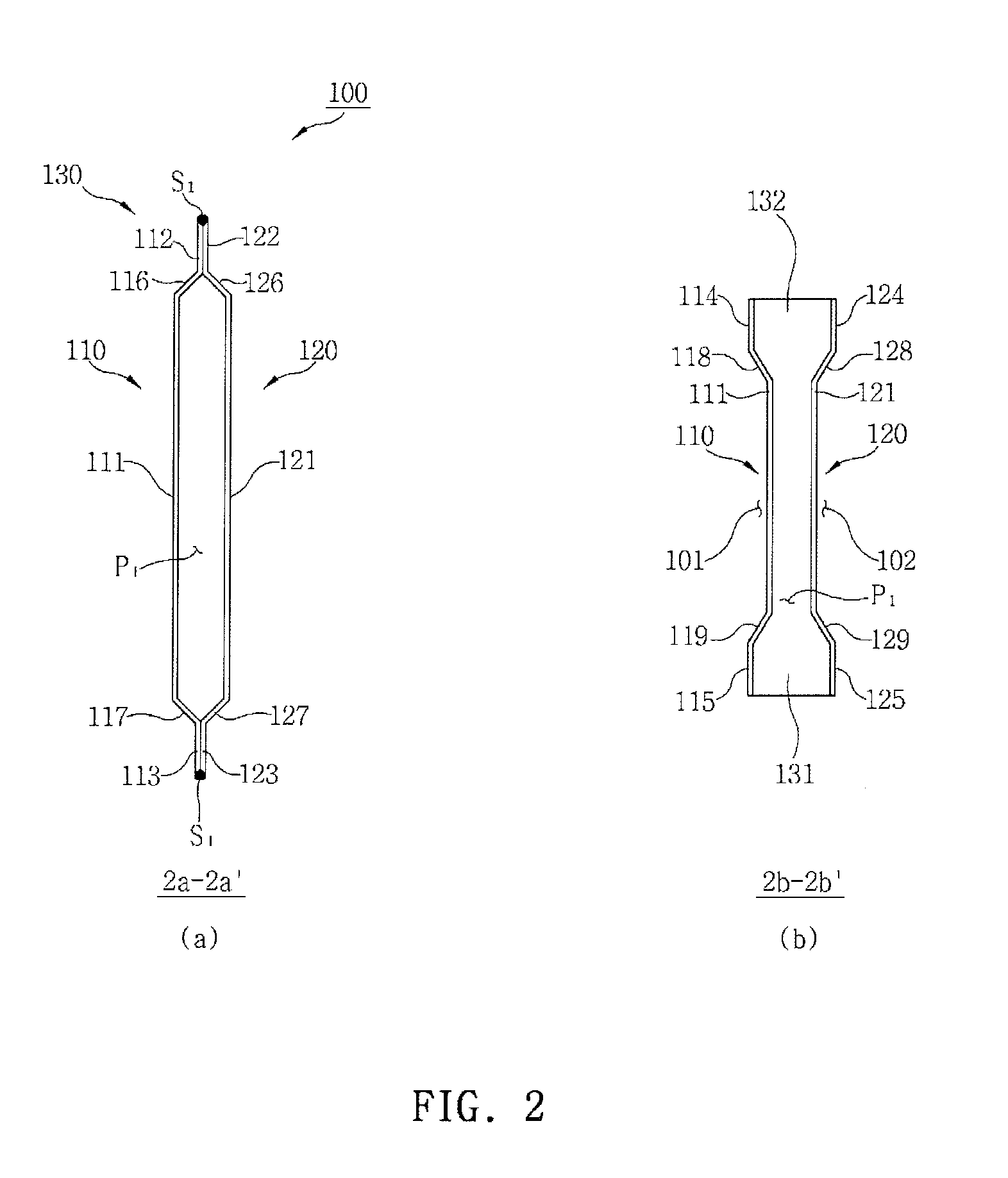
[0078]According to the present invention, as illustrated in FIGS. 1 and 2, the heat transfer cell 100 includes a cell body 130 having a first (or transverse) fluid passage P1, i.e. an internal fluid passage, through which a fluid flows in one direction. The cell body 130 is obtained by welding a pair of heat transfer plates 110 and 120, which are opposite to each other in a mirror image.

[0079]The heat transfer plate 110 or 120 includes a heat transfer area 111 or 121 shaped of a substantially quadrilateral panel, a pair of first flanges 112 and 113, or 122 and 123 bent from opposite upper and lower edges of the heat transfer area 111 or 121 in one direction when viewed from FIG. 1 and having a height difference with respect to the heat transfer area 111 or 121, and a pair of second flanges 114 and 115, or 124 and 125 bent from opposite left-hand and right-hand edges of the heat transfer area 111 or 121 in the direction opposite the bending direction of the first flanges 112 and 113,...

second embodiment

[0097]According to the present invention, as illustrated in FIGS. 4 and 5, the heat transfer cell 100a includes a cell body 130a having a first fluid passage P1, i.e. an internal fluid passage, through which a fluid flows in one direction, by welding a pair of heat transfer plates 110a and 120a, which are opposite to each other in a mirror image.

[0098]As in the first embodiment, the heat transfer plates 110a and 120a includes a pair of first flanges 112a and 113a, or 122a and 123a and a pair of second flanges 114a and 115a, or 124a and 125a, each of which is bent and extends in a direction perpendicular to each other and has a height difference with respect to the heat transfer area 111a or 121a shaped of a substantially quadrilateral panel.

[0099]The cell body 130a includes the first fluid passage P1 therein which has open opposite ends by welding the heat transfer plates 110a and 120a that are opposite to each other in a mirror image, weld lines S2 that weld and seal faying surface...


PUM

PropertyMeasurementUnit
temperatureaaaaaaaaaa
heightaaaaaaaaaa
angleaaaaaaaaaa

Abstract

A heat transfer cell includes first and second heat transfer plates which have first and second heat transfer areas, and first and second flanges bent from the first and second heat transfer areas so as to have a height difference with respect to the first and second heat transfer areas. The first and second heat transfer plates are joined into a cell body so as to be opposite to each other in a mirror image, and the cell body having a first fluid passage therein, weld lines formed along the first contacting each other and along the second flanges contacting each other, and external recesses formed outside the heat transfer areas for second fluid passages intersecting with the first fluid passage at a right angle.

Description

CROSS-REFERENCE TO RELATED APPLICATIONS[0001]This application claims the priority of Korean Patent Application No. 2008-0066435, filed on Jul. 9, 2008, in the Korean Intellectual Property Office, the disclosure of which is incorporated herein by reference.BACKGROUND OF THE INVENTION[0002]1. Field of the Invention[0003]The present invention relates to a heat transfer cell and assembly for a heat exchanger and methods of fabricating the same, and more particularly, to a heat transfer cell and assembly for a heat exchanger and methods of fabricating the same, capable of minimizing vortex at and in the inlet of a passage into and through which a fluid flows, increasing a contact area between the fluid and its contact plate to improve heat exchange efficiency, easily and rapidly fabricating an assembly by stacking a plurality of heat transfer cells to improve productivity, preventing welding defects resulting from downward sagging of the heat transfer plate when the heat transfer cells a...

Claims


Application Information

Patent Timeline
Patent Type & Authority Applications(United States)
IPC IPC(8): F28F3/08B21D53/02
CPCF28D9/0037F28F1/006F28F1/045Y10T29/49366F28F2275/06Y10T29/4935F28F3/10F28F19/00F28F3/00F28F3/02F28F3/12B23P15/26
Inventor CHO, MUN-JAE
Owner EURO - APEX
Why Eureka
Try Eureka