High transmission power using shared bluetooth and wireless local area network front end module

a technology of shared bluetooth and front end module, which is applied in the field of data communication, can solve the problems of inability to meet the needs of users, etc., and achieve the effect of reducing the amount of pcb real estate required, and reducing the cost of pcb real esta

Inactive Publication Date: 2010-01-14
TEXAS INSTR INC
View PDF7 Cites 113 Cited by
  • Summary
  • Abstract
  • Description
  • Claims
  • Application Information

AI Technical Summary

Benefits of technology

[0030]The shared FEM mechanism of the invention provides several advantages, including: (1) the ability to provide class 1 emission levels to the Bluetooth core without requiring a separate FEM (i.e. the power amplifier for WLAN transmission already supports this); (2) the ability to bypass the shared power amplifier for low power Bluetooth transmission purposes; (3) the ability to use a conventional FEM in the case the switching control is incorporated in the radio module; (4) the reduction in cost, power consumption, PCB real estate required and bill of materials (BOM) achieved by sharing the single power amplifier in the FEM between both WLAN and Bluetooth radios.

Problems solved by technology

Because devices operate in the unlicensed 2.4 GHz RF band, they are subject to radio interference from other wireless devices operating in the same frequency band.
Data packets, when transmitted over networks, are frequently susceptible to delays by, for example, retransmissions of packets caused by errors, sequence disorders caused by alternative transmission pathways, etc.
Packet delays or dropped packets during the transmission of voice signals, however, can cause unacceptable quality of service.
Bandwidth limitations limit the Bluetooth specification to a maximum of three SCO links.
Radio interference occurs when Bluetooth and WLAN devices try to communicate simultaneously over the same RF band.
As Bluetooth personal area networks and WLANs use the same ISM RF band of 2.4 GHz to 2.5 GHz, radio interference between the different devices can degrade network communications, e.g., decreased data throughput and quality of voice service caused by retransmissions resulting from interference.

Method used


Image

  • High transmission power using shared bluetooth and wireless local area network front end module
  • High transmission power using shared bluetooth and wireless local area network front end module
  • High transmission power using shared bluetooth and wireless local area network front end module

Examples


first embodiment

with Duplicate Power Amplifiers

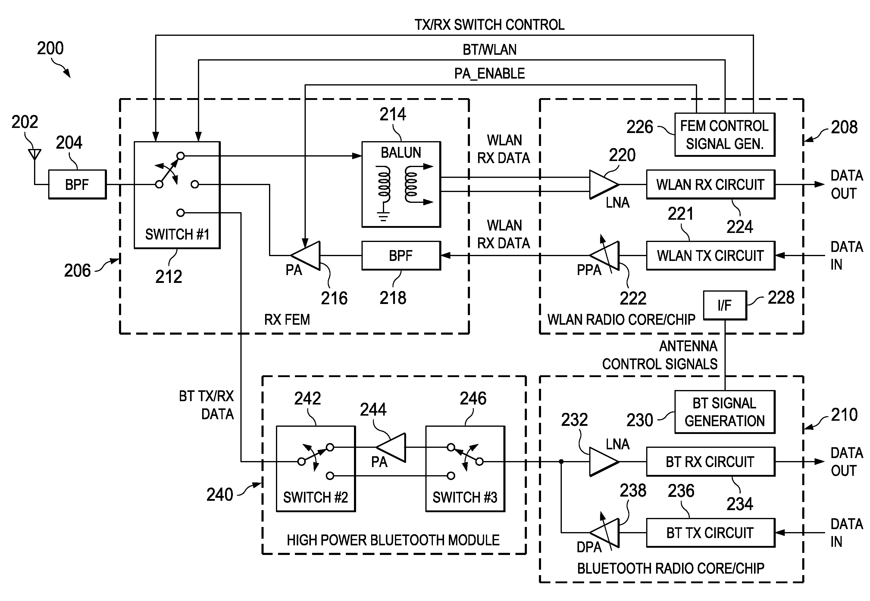
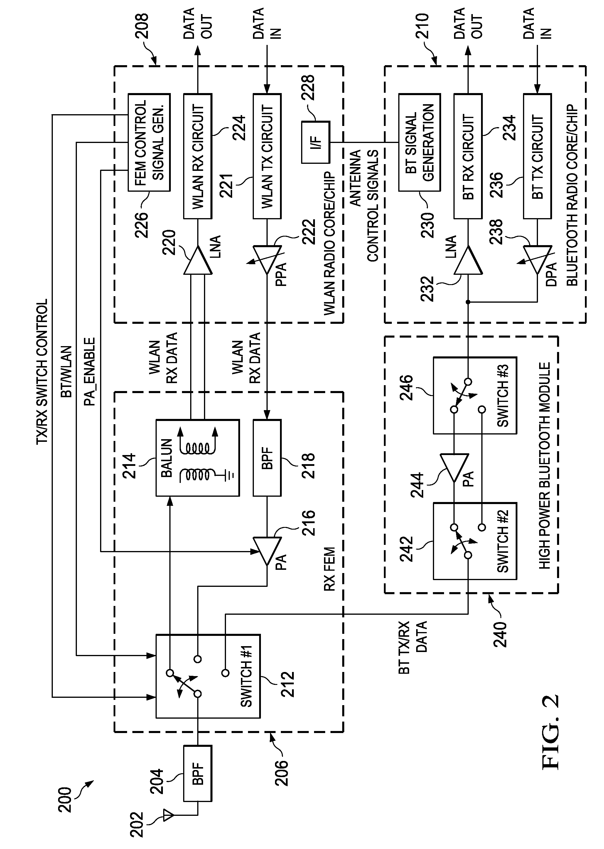
[0069]A block diagram illustrating a first example WLAN / Bluetooth high power transmission scheme is shown in FIG. 2. The system, generally referenced 200, comprises a WLAN radio core / chip 208, Bluetooth radio core / chip 210, RF FEM 206, external high power Bluetooth module 240, band pass filter (BPF) 204 and antenna 202. The WLAN radio core comprises, in a receive path, LNA 220 which receives the WLAN RX data signal and WLAN RX circuit 224 which generates the data out signal, and in a transmit path, comprises WLAN TX circuit 221 receiving a data in signal and pre-power amplifier (PPA) 222 which generates the WLAN TX data signal. The WLAN radio core also comprises an interface block 228 for sending / receiving one or more signals to / from the Bluetooth signal generation block 230, and FEM control signal generator 226 which functions to generate the appropriate FEM control signals, namely TX / RX switch control, BT / WLAN and PA_ENABLE.

[0070]The Bluetooth radio ...

second embodiment

with Shared Power Amplifier

[0075]A block diagram illustrating a second example WLAN / Bluetooth high power transmission scheme is shown in FIG. 3. The system, generally referenced 250, comprises a WLAN / Bluetooth chip 262, incorporating a WLAN radio core 258 and a Bluetooth radio core 260, an RF FEM 256, band pass filter (BPF) 254 and antenna 252. The WLAN radio core comprises, in a receive path, LNA 276 which receives the WLAN RX data signal and WLAN RX circuit 278 which generates the data out signal, and in a transmit path, comprises WLAN TX circuit 280 receiving a data in signal and pre-power amplifier (PPA) 282 which generates the WLAN TX data signal. The WLAN radio core also comprises an interface block 284 for sending / receiving one or more signals to / from the Bluetooth signal generation block 286, and FEM control signal generator 274 which functions to generate the appropriate FEM control signals, namely TX / RX switch control, BT / WLAN and PA_ENABLE.

[0076]The Bluetooth radio core c...

third embodiment

with Duplicate Power Amplifiers

[0085]A block diagram illustrating a third example WLAN / Bluetooth high power transmission scheme is shown in FIG. 8. The system, generally referenced 350, comprises an RF FEM 356, band pass filter (BPF) 354, antenna 352 and a WLAN / Bluetooth chip 362 incorporating a WLAN radio core 358, a Bluetooth radio core 360 and switch #2380,. The WLAN radio core comprises, in a receive path, LNA 370 which receives the WLAN RX data signal and WLAN RX circuit 372 which generates the data out signal, and in a transmit path, comprises WLAN TX circuit 374 receiving a data in signal and pre-power amplifier (PPA) 376 which generates the WLAN TX data signal. The WLAN radio core also comprises an interface block 400 for sending / receiving one or more signals to / from the Bluetooth signal generation block 402, and FEM control signal generator 378 which functions to generate the switch #2 control signal and the appropriate FEM control signals, namely TX / RX switch control, BT / W...


PUM


Abstract

A novel and useful system for providing high transmission power using a shared Bluetooth and Wireless Local Area Network (WLAN) front end module (FEM). A single power amplifier in the front end module is shared between the WLAN and Bluetooth radio cores, thus providing a high power transmission option (Bluetooth class 1) for the Bluetooth core. Interface circuitry in the FEM couple either the WLAN TX output or the Bluetooth TX output to the input of the power amplifier and couple the output of the power amplifier to the external antenna. In the receive direction, the interface circuitry steers the antenna input to the respective WLAN or Bluetooth receivers in accordance with one or more control signals. Alternatively, a switch in the WLAN/Bluetooth radio chip functions to switch the Bluetooth TX output to a conventional FEM, thereby allowing the FEM power amplifier to be shared between the WLAN and Bluetooth radio cores.

Description

FIELD OF THE INVENTION[0001]The present invention relates to the field of data communications and more particularly relates to a system for providing high transmission power using a shared Bluetooth and Wireless Local Area Network (WLAN) front end module (FEM).BACKGROUND OF THE INVENTION[0002]Currently, there is huge demand for converged mobile devices which combine data and telephony capabilities. Technological advances such as extremely low power consumption, improvements in form factor, pricing and co-existence technology for 802.11 (WLAN) and Bluetooth are fueling the demand.[0003]Wireless communication devices such as WLAN and Bluetooth devices are generally constrained to operate in a certain frequency band of the electromagnetic spectrum. The use of frequency bands is licensed by government regulatory agencies, for example, the U.S. Federal Communications Commission (FCC) and the European Radio Communications Office. Licensing is necessary in order to prevent interference bet...

Claims


Application Information

Patent Timeline
Patent Type & Authority Applications(United States)
IPC IPC(8): H04Q7/24H04B7/00
CPCH04B1/006H04B1/0067H04W88/06H04W72/1215H04B1/406
Inventor TSFATI, YOSSISHERLOCK, IANELIEZER, OREN E.
Owner TEXAS INSTR INC
Why Eureka
Try Eureka