Cavity-enhanced photo acoustic trace gas detector with improved feedback loop

Inactive Publication Date: 2010-01-21
KONINKLIJKE PHILIPS ELECTRONICS NV
View PDF10 Cites 35 Cited by
  • Summary
  • Abstract
  • Description
  • Claims
  • Application Information

AI Technical Summary

Benefits of technology

[0008]When choosing the chopping frequency higher than the modulation frequency, the light is turned on and off multiple times during one period of the modulation of the wavelength or cavity length. The effect of the obstruction of the light beam will then be averaged over one period of the wavelength modulation and there are no long periods where the feedback signal is absent. The response time of the feedback loop can be much faster than in the previously known photo acoustic trace gas detectors with optical cavity.
[0009]Preferably, the chopping frequency is at least three times higher than the modulation frequency, for achieving the most advantageous effect.
[0010]In a preferred embodiment the transducer is a crystal oscillator. A crystal oscillator is much more sensitive than the microphone used in the above mentioned prior art s

Problems solved by technology

This excitation leads to an increase of the thermal energy, resulting in a local rise of the temperature and the pressure inside the acoustic cell.
As a result, the system can run out of its lock-loop for sudden disturbances, because it cannot respond sufficiently fast.
Currently, exhaled NO levels at ppb concentrations can be only measured using expensive and bulky equipment based on chemiluminescence or far infrared optical absorption spectroscopy.
It is the challenge for these hand-held gas-analyzing devices to combine sufficient high s

Method used


Image

  • Cavity-enhanced photo acoustic trace gas detector with improved feedback loop
  • Cavity-enhanced photo acoustic trace gas detector with improved feedback loop
  • Cavity-enhanced photo acoustic trace gas detector with improved feedback loop

Examples


Example

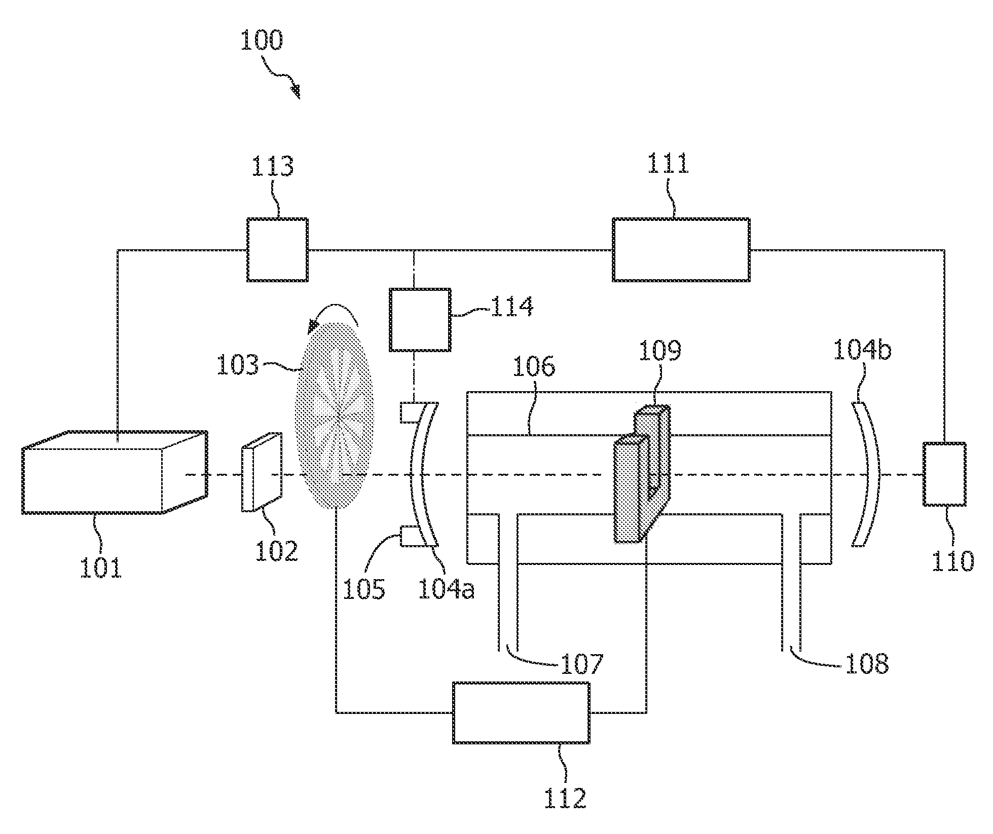
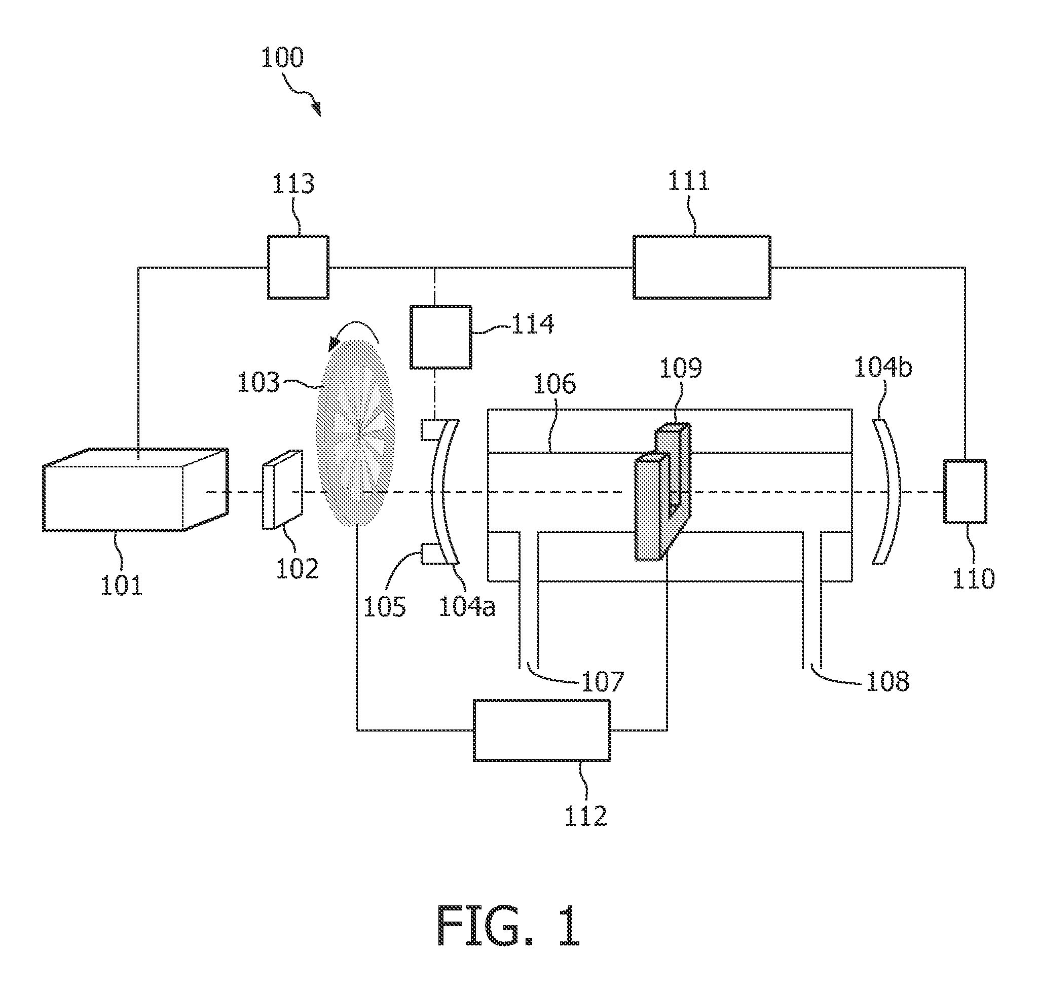
[0018]FIG. 1 shows a typical photo acoustic trace gas detector according to the invention. A light source 101 provides a continuous wave laser beam and is modulated into a series of light pulses at a certain ‘chopping’ frequency by, e.g., a chopper 103, shutter or acousto-optic modulator. At higher chopping frequencies (>6 kHz), acousto-optic modulators are preferably used instead of a mechanical chopper. Alternatively, the light source 101 itself may provide the light pulses at a fixed chopping frequency. The light pulses are sent into an optical cavity, which is defined by two semi-transparent mirrors 104a and 104b. An optical isolator 102 is optionally placed between the light source 101 and the input mirror 104a to reduce the back reflectance of light from the cavity mirror 104a into the light source 101. The light pulses enter the optical cavity through input mirror 104a and are reflected many times between the two cavity mirrors 104a and 104b. If the distance between the two m...


PUM


Abstract

A photo acoustic trace gas detector (100) is provided for detecting a concentration of a trace gas in a gas mixture. The detector (100) comprises a light source (101) for producing a light beam and a light modulator (103) for modulating the light beam into a series of light pulses at a chopping frequency for generating sound waves in the gas mixture. The amplitude of the sound waves is a measure of the concentration of the trace gas. The detector (100) further comprises an optical cavity (104a, 104b) with the gas mixture. The optical cavity (104a, 104b) amplifies the light intensity of the light pulses. A transducer (109) converts the sound waves into electrical signals. A feed back loop (110, 111, 113, 114) regulates a ratio of a length of the optical cavity (104a, 104b) and a wavelength of the light beam for amplifying the light intensity of the light pulses in the optical cavity (104a, 104b). The feedback loop (110, 111, 113, 114) comprises ratio modulating means (113, 114) for modulating the ratio at a modulation frequency, a photo detector (110) for measuring the light intensity of the light pulses and adjusting means (111), coupled to the photo detector (100) and to the ratio modulating means (113, 114) for, in dependence of the measured light intensity, adjusting an average of the ratio. The chopping frequency is higher than the modulation frequency.

Description

TECHNICAL FIELD OF THE INVENTION[0001]The invention relates to a photo acoustic trace gas detector for detecting a concentration of a trace gas in a gas mixture, the photo acoustic trace gas detector comprising a light source for producing a light beam, a light modulator for modulating the light beam into a series of light pulses at a chopping frequency for generating sound waves in the gas mixture, an amplitude of the sound waves being a measure of the concentration an optical cavity for containing the gas mixture and for amplification of a light intensity of the light pulses, a transducer for converting the sound waves into electrical signals, and a feedback loop for regulating a ratio of a length of the optical cavity and a wavelength of the light beam for the amplification of the light intensity of the light pulses in the optical cavity, the feedback loop comprising ratio modulating means for modulating the ratio at a modulation frequency, a photo detector for measuring the ligh...

Claims


Application Information

Patent Timeline
IPC IPC(8): G01N21/17
CPCG01N21/1702G01N29/2425G01N2291/0427G01N2021/1708G01N2021/1704
Inventor KALKMAN, JEROENVAN HERPEN, MAARRTEN MARINUS JOHANNES WILHELMVAN KESTEREN, HANS WILLEM
Owner KONINKLIJKE PHILIPS ELECTRONICS NV
Why Eureka
Try Eureka