Ultrasonic transducer

a transducer and ultrasonic technology, applied in the direction of liquid/fluent solid measurement, sound producing device, using ultrasonic/ultrasonic/infrasonic waves to analyze solids, etc., can solve the problem of ultrasonic signals being cross-talked, the proportion of transmission power is “lost”, and the total created oscillation energy is very low. problem, to avoid the effect of cross-talk

Active Publication Date: 2010-01-21
KRONE GMBH
View PDF11 Cites 16 Cited by
  • Summary
  • Abstract
  • Description
  • Claims
  • Application Information

AI Technical Summary

Benefits of technology

[0010]A primary object of the present invention is, thus, to provide an ultrasonic transducer for installation in an instrument housing, which im

Problems solved by technology

It is a problem for measurements based on emitted acoustic or ultrasonic signals, not only in the field of mass flow measurement, that the ultrasonic oscillation created in the ultrasonic transducer are not only transmitted by the emitting and/or receiving side of the transducer housing in the surrounding medium of the ultrasonic transducer, but that the created oscillations are transmitted to the instrument housing via the transducer housing—as the case may be, via the housing fixture, insofar as it differs from the instrument housing.
This is not only a problem because, under certain circumstances, a considerable portion of the transmission power is “lost”, rather is a problem because the ultrasonic waves transmitted to the instrument housing by so-called crosstalk can lead to considerable receiving-side interference.
In particular, in gas applications, in which the medium is comprised of gas, the portion of the oscillation energy

Method used


Image

  • Ultrasonic transducer
  • Ultrasonic transducer
  • Ultrasonic transducer

Examples


Embodiment Construction

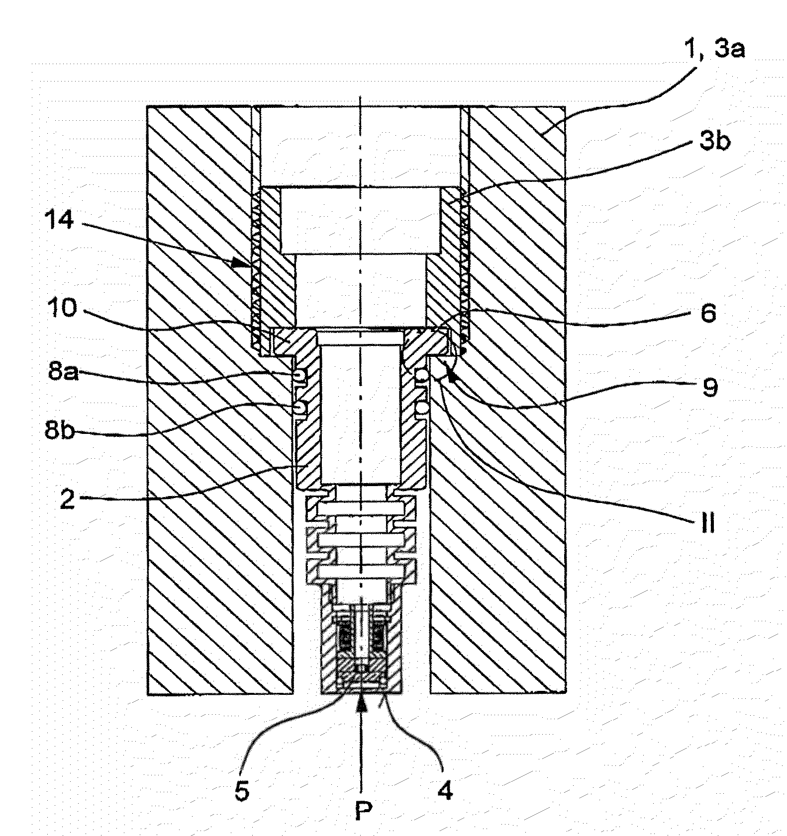
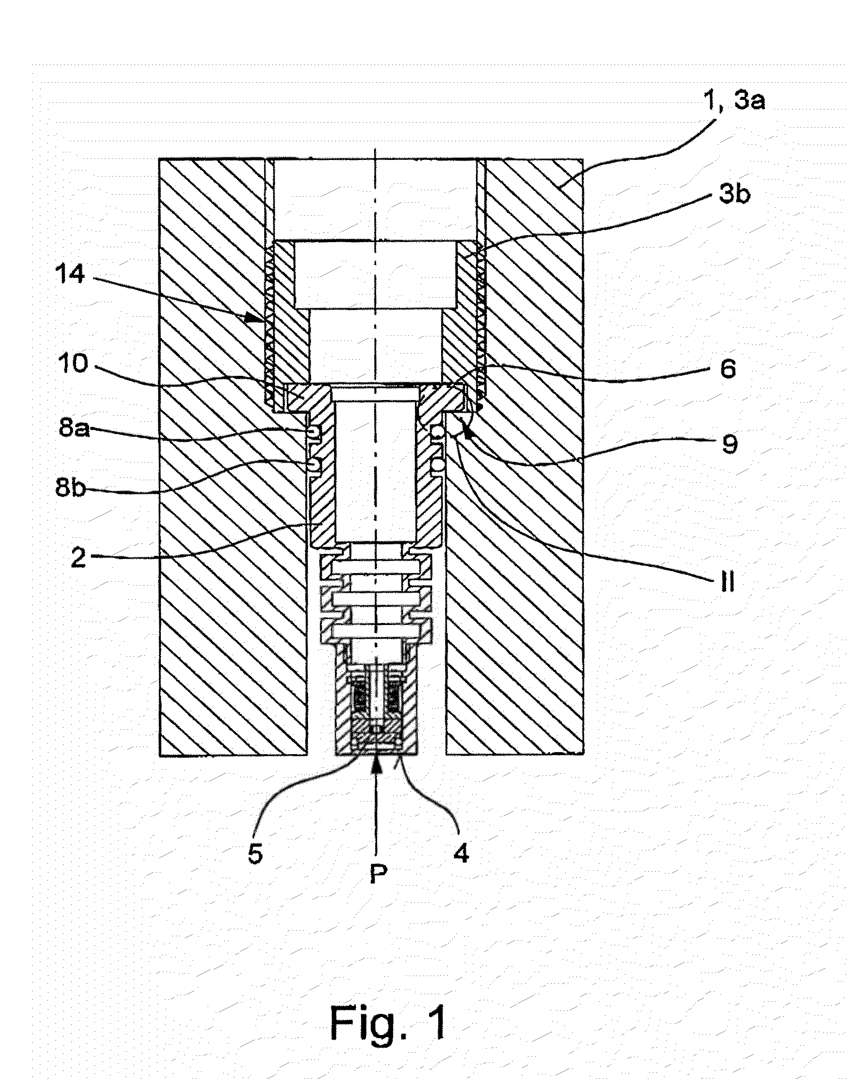
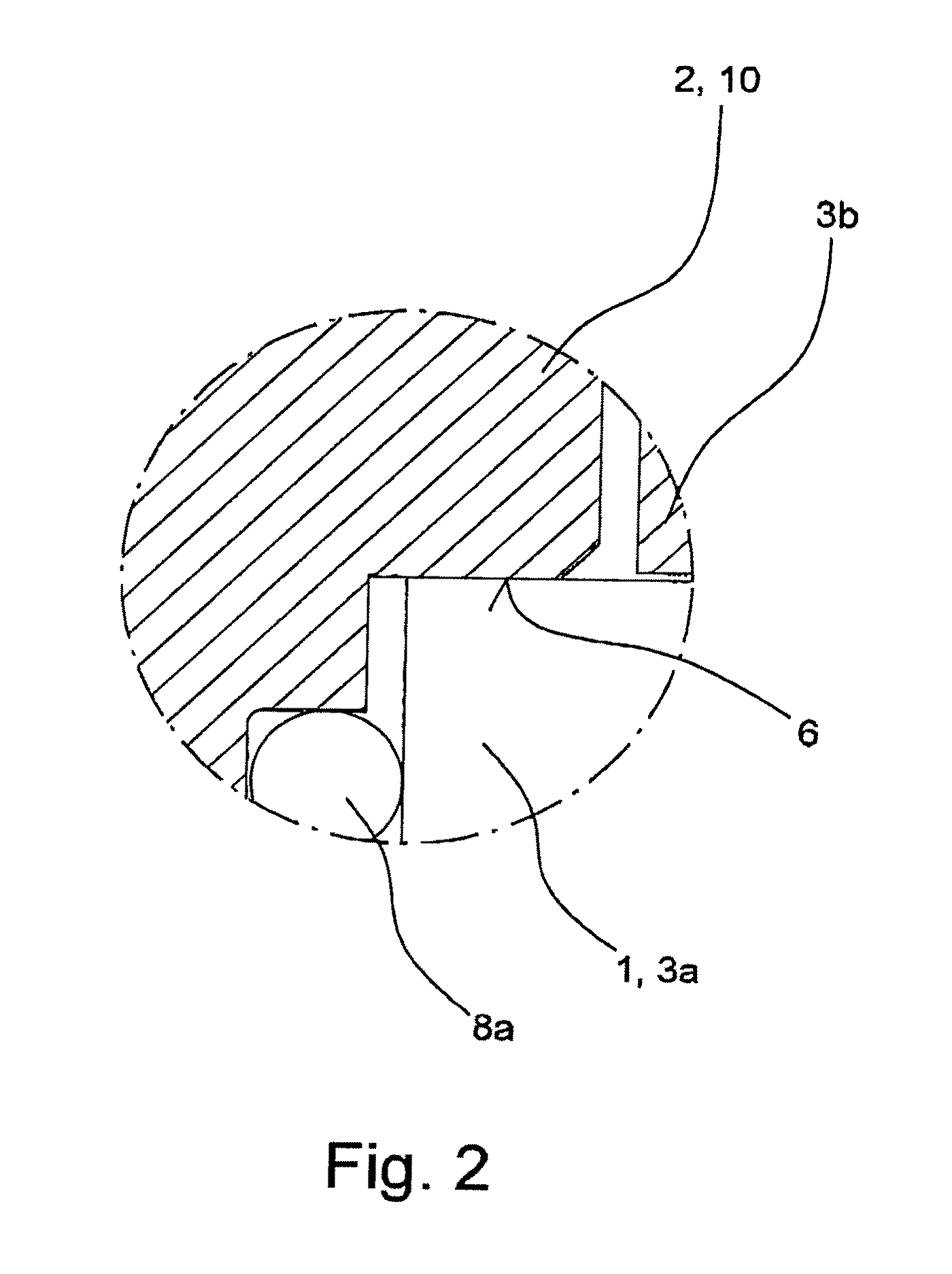
[0029]FIGS. 1 to 4 show an ultrasonic transducer according to the invention, which is provided for installation in an instrument housing 1, wherein the instrument housing 1 is only illustrated in FIGS. 1 to 3. The ultrasonic transducer comprises a transducer housing and a housing fixture, wherein the transducer housing can be put under the pressure of a medium in its installed state on its emitting and / or receiving side; the medium is not explicitly illustrated in the figures.

[0030]The figures are schematic insofar as that only the constituents of interest of the ultrasonic transducer are shown. For example, the wiring of the actual ultrasonic exciter 5 is not shown, which is implemented as a piezo-element in the embodiments. It is presently not of importance whether the transducer housing 2 is made of one or two parts, how the head of the ultrasonic transducer is constructed in detail, and for example, of which material the ultrasonic transducer is made on its emitting and / or recei...


PUM


Abstract

An ultrasonic transducer for installation in an instrument housing, the ultrasonic transducer having a transducer housing and a housing fixture, the transducer housing being put under pressure by a medium in its installed state on its emitting and/or receiving side. To provide an ultrasonic transducer for installation in an instrument housing, which implements a measure for avoiding crosstalk of ultrasonic signals and avoids the disadvantages known from the prior art—at least partially, the ultrasonic transducer is wherein the transducer housing indirectly forms at least one contact area in its installed state with the housing fixture, the transducer housing and the housing fixture being at least indirectly pressed against one another in a first contact area with existing, but as slight as possible, surface pressure by a pre-loading mechanism.

Description

BACKGROUND OF THE INVENTION[0001]1. Field of Invention[0002]The invention relates to an ultrasonic transducer for installation in an instrument housing, wherein the ultrasonic transducer comprises a transducer housing and a housing fixture and wherein the transducer housing can be put under a medium pressure in its installed state on its emitting and / or receiving side.[0003]2. Description of Related Art[0004]Ultrasonic transducers of the above-mentioned type have been known for years and are, for example, used in acoustic mass flowmeters to a wide extent. The ultrasonic transducer transforms electric energy in the oscillation of a membrane that is provided on the emitting and / or receiving side in the transducer housing; in this case, the ultrasonic transducer acts as an ultrasonic emitter. By the same token, it is also possible that a membrane provided on the emitting and / or receiving side is oscillated by external—occurring in the medium—pressure fluctuations and the oscillation is...

Claims


Application Information

Patent Timeline
IPC IPC(8): G01N29/04
CPCG10K11/004G01F1/662H04R1/32H04R17/00
Inventor VAN KLOOSTER, JEROEN MARTINHUIJZER, ARIE
Owner KRONE GMBH
Why Eureka
Try Eureka