
Homogeneous Charge Compressed Ignition Engine Operating Method

a compression ignition and hydrogen charge technology, applied in the direction of machines/engines, automatic control of ignition, electrical control, etc., can solve the problems of long time to lower or raise, difficult to control ignition timing, and problems in practical use, so as to achieve the effect of reducing the operating range of compression ignition, and reducing the time of ignition

Inactive Publication Date: 2010-01-21
YANMAR POWER TECHNOLOGY CO LTD
View PDF7 Cites 14 Cited by
  • Summary
  • Abstract
  • Description
  • Claims
  • Application Information

AI Technical Summary

Benefits of technology

[0018]According to the invention, the utilization of the spark-assist compression ignition operation in which the spark ignition is supplementarily used can smoothly and shortly make the transition between the spark ignition operation and the compression ignition operation (non-spark compression ignition operation) according to the magnitude of the load while the intake air temperature is substantially kept constant. The operation range of the compression ignition can substantially be enlarged by performing the spark-assist compression ignition operation.
[0019]Accordingly, in the configuration (1), when the load is not lower than the predetermined value, feedback control is performed based on the comparison of the target compression ignition timing and actual compression ignition timing, which allows the spark ignition timing to be adjusted at proper timing. On the other hand, the actual compression ignition timing is hardly detected when the load is not more than the predetermined value, and the spark ignition timing is fluctuated to easily generate the knocking when the feedback control is performed. Therefore, the spark ignition can be performed more stably by performing the spark ignition at the timing selected from the spark ignition timing map.
[0020]Accordingly, in the configuration (2), the engine is quickly warmed from the cold state to the warm state, so that the intake air temperature can quickly be raised by utilizing the engine cooling water or other things and therefore the state in which the load is fed can be formed.
[0021]Accordingly, in the configuration (3), the engine is quickly warmed from the cold state to the warm state, so that the intake air temperature can quickly be raised to form the state in which the load is fed.
[0022]Accordingly, in the configuration (4), the engine speed can be governed by the throttle valve even if throttle valve opening becomes more than the predetermined value during the high load.
[0023]Accordingly, in the configuration (5), when the catalytic conversion performance can insufficiently be exerted due to the low exhaust gas temperature like the case of the low load operation, the exhaust gas temperature is raised while the engine speed is maintained, which allows the catalytic conversion efficiency to be enhanced.

Problems solved by technology

However, in the homogeneous charge compressed ignition engine, because the mixture gas is naturally ignited, it is extremely difficult to control ignition timing.
Accordingly, it takes a long time to lower or raise the intake air temperature until the load is fed or the load is completely cut off since the intake air temperature is raised, which results in a problem in practical use.
Therefore, in the case where the feed or cutoff of the load is performed at the intake air temperature set as shown by the arrow Y3 of FIG. 3, the fuel concentration becomes weak during the low load in the governing in which the fuel control valve is used, which results in a problem in that self-ignition is not generated.
However, in such cases, the throttle is opened near a fully open state when the load is increased, and a mixture gas amount is hardly changed even if the throttle opening is varied, which results in a problem in that a speed control insufficiently functions.
This is attributed to the fact that, as shown in FIG. 12(A), an exhaust gas temperature is lowered to insufficiently promote a chemical reaction for purifying the air-pollution substance when the load is decreased.

Method used


Image

  • Homogeneous Charge Compressed Ignition Engine Operating Method
  • Homogeneous Charge Compressed Ignition Engine Operating Method
  • Homogeneous Charge Compressed Ignition Engine Operating Method

Examples


Embodiment Construction

[0045][Outline of Homogeneous Charge Compressed Ignition Engine]

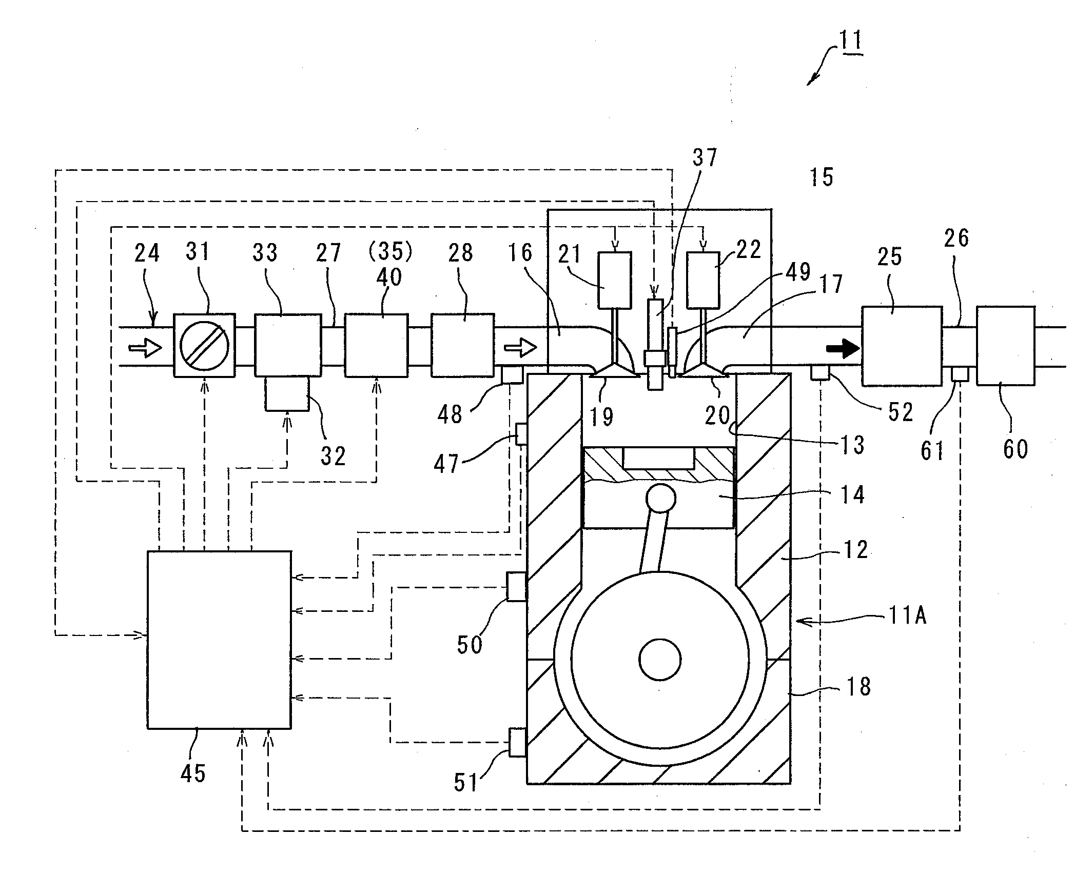
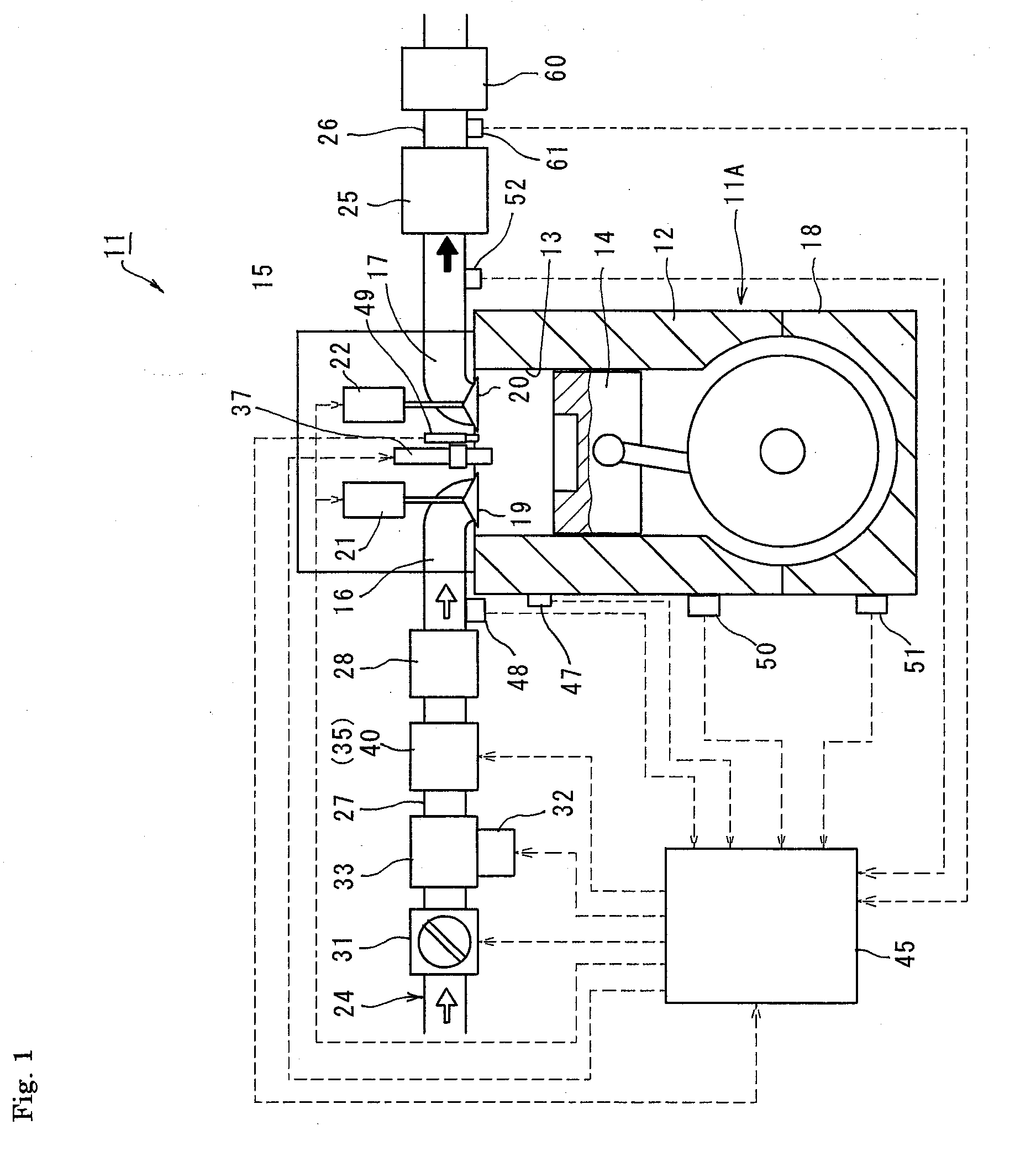
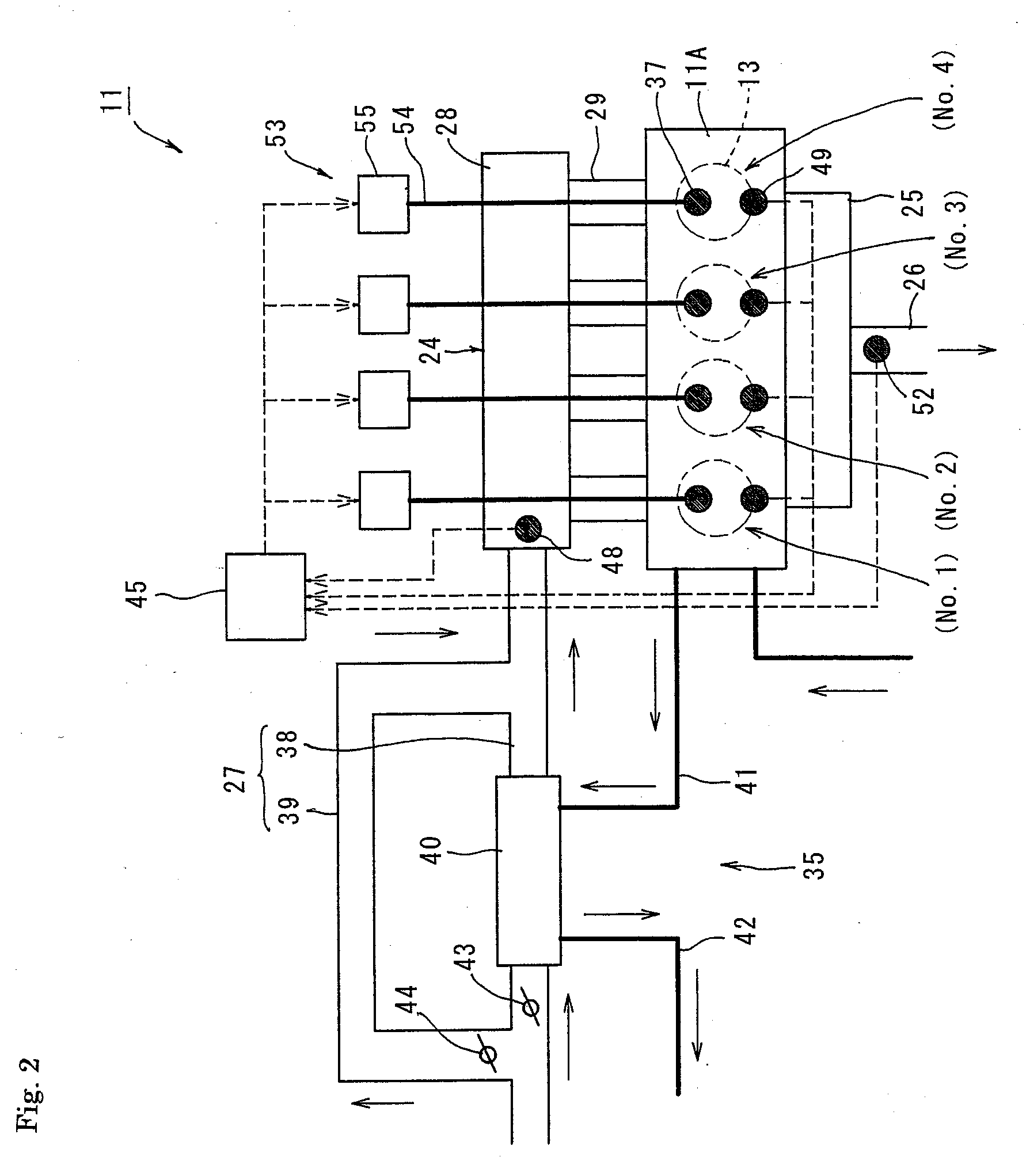
[0046]FIG. 1 is a sectional view schematically showing a homogeneous charge compressed ignition engine 11 according to an embodiment of the invention, and FIG. 2 is a plan view schematically showing the homogeneous charge compressed ignition engine 11. The homogeneous charge compressed ignition engine 11 of the embodiment is a four-cylinder (No.1 to No.4) four-cycle engine, and the homogeneous charge compressed ignition engine 11 has an engine body 11A including a cylinder block 12, a cylinder head 15, and a crankcase 18. A plurality of (four) cylinders 13 are provided in the cylinder block 12, and a piston 14 is slidably fitted in each cylinder 13. An intake port 16 and an exhaust port 17 are provided in the cylinder head 15. The intake port 16 and the exhaust port 17 are opened and closed by an intake valve 19 and an exhaust valve 20, respectively. The intake valve 19 and the exhaust valve 20 are driven by valve mecha...


PUM


Abstract

An aspect of the invention provides a method for operating a workable homogeneous charge compressed ignition engine in which a compression ignition operation is performed by spark ignition to shorten a load input time and a load cutoff time. In the homogeneous charge compressed ignition engine operating method, a mixture gas is burned by compression ignition in a combustion chamber, and fuel and air are previously mixed to produce the mixture gas. The homogeneous charge compressed ignition engine includes a spark ignition device 53 which performs spark ignition to the mixture gas. A temperature controller 35 substantially keeps an intake air temperature of the mixture gas constant. A spark ignition operation, a spark-assist compression ignition operation in which spark ignition is supplementarily used, and a non-spark compression ignition operation in which the spark ignition is not used are switched according to magnitude of a load.

Description

TECHNICAL FIELD [0001]The present invention relates to a homogeneous charge compressed ignition (HCCI) engine operating method.BACKGROUND ART[0002]In this kind of engine, for example, Patent Document 1 discloses a homogeneous charge compressed ignition engine, wherein a mixture gas in which fuel and air are previously mixed is supplied to a combustion chamber in a cylinder to compress the mixture gas, thereby self-igniting the mixture gas. Patent Document 1 also discloses that a spark ignition operation (SI operation) is performed in engine starting in which a compression ignition operation is hardly performed.[0003]The homogeneous charge compressed ignition engine has an advantage that thermal efficiency is high because operation can be performed at a compression ratio higher than that of a spark ignition type engine. Generation of NOx can also be restrained because a combustion temperature can be lowered. However, in the homogeneous charge compressed ignition engine, because the m...

Claims


Application Information

Patent Timeline
IPC IPC(8): F02B17/00F02P5/04F01N3/10
CPCF02D41/0002F02D41/064F02D41/3041Y02T10/42F02D2200/0414Y02T10/128F02D41/3076F02D41/3035Y02T10/12Y02T10/40F02B19/12F02B19/14F02D41/04F02D37/02
Inventor NAKAZONO, TOHRUOHTSUBO, HIROYUKISHIROUZU, TAKAYUKI
Owner YANMAR POWER TECHNOLOGY CO LTD
Learn More