Mr magnetometer with combined flip coil and compensation coil

Inactive Publication Date: 2010-01-21
BREAKWATERS INNOVATIONS
View PDF2 Cites 11 Cited by
  • Summary
  • Abstract
  • Description
  • Claims
  • Application Information

AI Technical Summary

Benefits of technology

[0015]An embodiment especially interesting to mobile applications of the invention is the one wherein the angle between the first main axis of the element and the second main axis of the MR sensor strip is substantially larger than 45° and smaller than 90°. For example, the angle has a value in the range of about 75° to 85°. A reason for this specific configuration has to do with power consumption. The flip coil functionality is being used more frequently than the compensation coil functionality, so that a

Problems solved by technology

In other words, the basic problem is that ideally both coils should be located as close as possible to the MR sensor.
Functional MR sensors without compensation coil are possible, although compensating through auxiliary fields is no longer an option.
Another disadvantage

Method used


Image

  • Mr magnetometer with combined flip coil and compensation coil
  • Mr magnetometer with combined flip coil and compensation coil
  • Mr magnetometer with combined flip coil and compensation coil

Examples


first embodiment

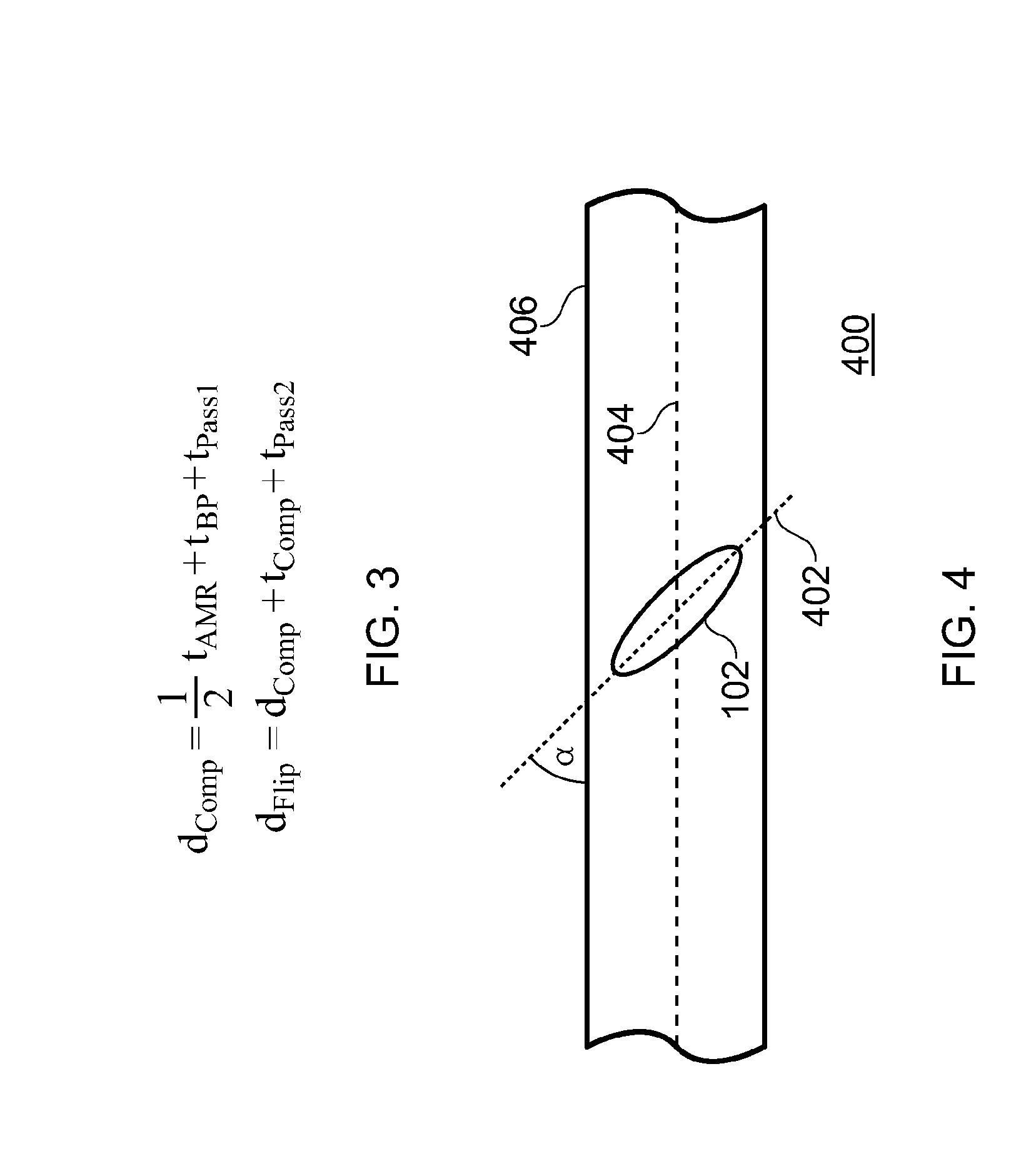
[0029]In the invention the angle α between the main axis of the element and the main axis of the sensor is about 45°. Then, efficiency numbers for the optimal case wherein α is 90° (previously denoted by the symbol “⊥”), should be multiplied by geometrical factors cos (45°)=1 / √2 and sin (45°)=1 / √2, for compensation and flip operations, respectively. As a result the efficiency GComp equals the efficiency GFlip and amounts to 3.48 A / m per mA.

[0030]For the compensation functionality, current pulses are used with small amplitude and of long duration, during which at least one magnetometer reading can take place. The amplitude is in the order of the strength of the earth-magnetic field (approx. 50 micro-Tesla), or lower. The pulse duration is in the millisecond range, or longer, in order to allow for a stable magnetometer reading.

[0031]For the flip functionality, current pulses are used with high amplitude and of short duration. As discussed before, this is to take place between consecut...

second embodiment

[0033]In the invention, the angle α can be given another value so that the configuration is optimized for low power consumption. Power consumption to be considered in this respect is related to the power dissipated during compensation operation and flip operation. Consider an angle α that is larger than 45°. For example, angle α is 75°. As a result the efficiency GComp of the compensation coil functionality is 1.27 A / m per mA, and the efficiency GFlip of the flip coil functionality is 4.75 A / m per mA. The ratio in efficiency for flip functionality and compensation functionality in this case is about a factor 4.

[0034]In power-optimized designs it is anticipated that this ratio will be in the order of 2 to 10. It is to be noted that the compensation operation occurs seldom, e.g. during the manufacturing final test and the sensor self-test. Therefore, the efficiency of the compensation operation need not be high at all. Moreover, the main aim of the compensation operation is to measure...


PUM


Abstract

Compensation coil functionality and flip coil functionality are combined into a single combination coil that is placed under an angle α with respect to the length direction of a magneto-resistive sensor element. The angle α substantially deviates from 0° and 90°. This configuration enables to reduce the width of the current line of the planar combination coil, to reduce the effective threshold for sensor element switching, and to include features to simplify a 2D sensor design.

Description

FIELD OF THE INVENTION[0001]The invention relates to an electronic device with an MR magnetometer that has a flip coil functionality and a compensation coil functionality.BACKGROUND ART[0002]Magneto-resistance (MR) is a material property of a whole family of ferromagnetic alloys that refers to a dependence of electrical resistance on the angle between the direction of the electrical current flowing through the material and the orientation of an external magnetic field relative to the direction of the current. The effect is attributed to a larger probability of s-d scattering of electrons in the direction of the magnetic field. The net effect is that the electrical resistance maximum value when the direction of current is parallel to the applied magnetic field. An example of such material is a ferromagnetic material called “permalloy” (19% Fe, 81% Ni).[0003]MR materials can be used to create magnetic field sensors, also referred to as magneto-meters. Operation and examples of such se...

Claims


Application Information

Patent Timeline
IPC IPC(8): G01R33/02
CPCB82Y25/00G01R33/096G01R33/093
Inventor BOEVE, HANS M.B.IKKINK, TEUNIS J.DURIC, HARISVAN LAMMEREN, JOHANNES P.M.
Owner BREAKWATERS INNOVATIONS
Why Eureka
Try Eureka