Immobilisation of fluorescent proteins

a fluorescent protein and protein technology, applied in the field of fluorescent resonance energy transfer, can solve the problems of changing the oxygen concentration in the sample, requiring encapsulation in a hydrophobic matrix, and further limiting the application of both types of sensors, so as to achieve enhanced quenching, gain in quantum yield of fluorescence, and sensitivity.

Inactive Publication Date: 2010-01-21
UNIV DEGLI STUDI DI PADOVA +1
View PDF3 Cites 3 Cited by
  • Summary
  • Abstract
  • Description
  • Claims
  • Application Information

AI Technical Summary

Benefits of technology

[0023]Case c) mentioned above has the particular advantage that it results in a gain in sensitivity: the intrinsic fluorescence of the protein is (partly) quenched and, in addition, the label fluorescence is (partly) quenched. Both of these quenching effects are the result of FRET to the acceptor moiety. The effects are cumulative and result in enhanced quenching. For instance, if the intrinsic protein fluorescence is quenched to 70% of its original fluorescence, and the label fluorescence quenches to 60%, the fluorescence of the label will exhibit an overall reduction to 42% of its original fluorescence level.
[0024]By a proper choice of the fluorescent label the present invention provides both a sensitive and selective method for the detection of an analyte. Since FRET efficiency depends on the inverse sixth power of the distance between emitter and absorber, energy transfer from other molecules is not efficient enough to compete with the intra-molecular energy transfer to the label. The advantage of measuring the sensitised fluorescence in particular is that the signal is free from background noise. Since the label can be chosen so that the emission occurs in the visible range of the spectrum where there is no interference from other emitting species in the solution, the method is selective. Moreover, depending on the efficiency of energy transfer, there may also be a gain in quantum yield of the fluorescence when comparing the sensitized fluorescence with the intrinsic fluorescence of the protein. This also helps to increase the sensitivity of the method proposed herein.
[0025]Immobilisation has the potential to provide a more stable and, above all, reusable sensor. The matrix can be selected to provide an appropriate environment for the protein, which allows it to maintain its native structure, spectroscopic properties and catalytic properties upon encapsulation into the matrix.

Problems solved by technology

One of the Clark electrode's drawbacks is that it consumes oxygen during measurement, thereby changing the oxygen concentration in the sample.
Such a compound has the drawback of being unstable in water and therefore requiring encapsulation in a hydrophobic matrix.
Application of both types of sensors is further limited because of possible interference by other substances and because of relatively long response times.

Method used


Image

  • Immobilisation  of fluorescent proteins
  • Immobilisation  of fluorescent proteins
  • Immobilisation  of fluorescent proteins

Examples


example 1

Protein Trp Fluorescence and O2 Binding (Reference)

[0109]To illustrate this Example, Ty from the soil bacterium Streptomyces antibiotius was selected.

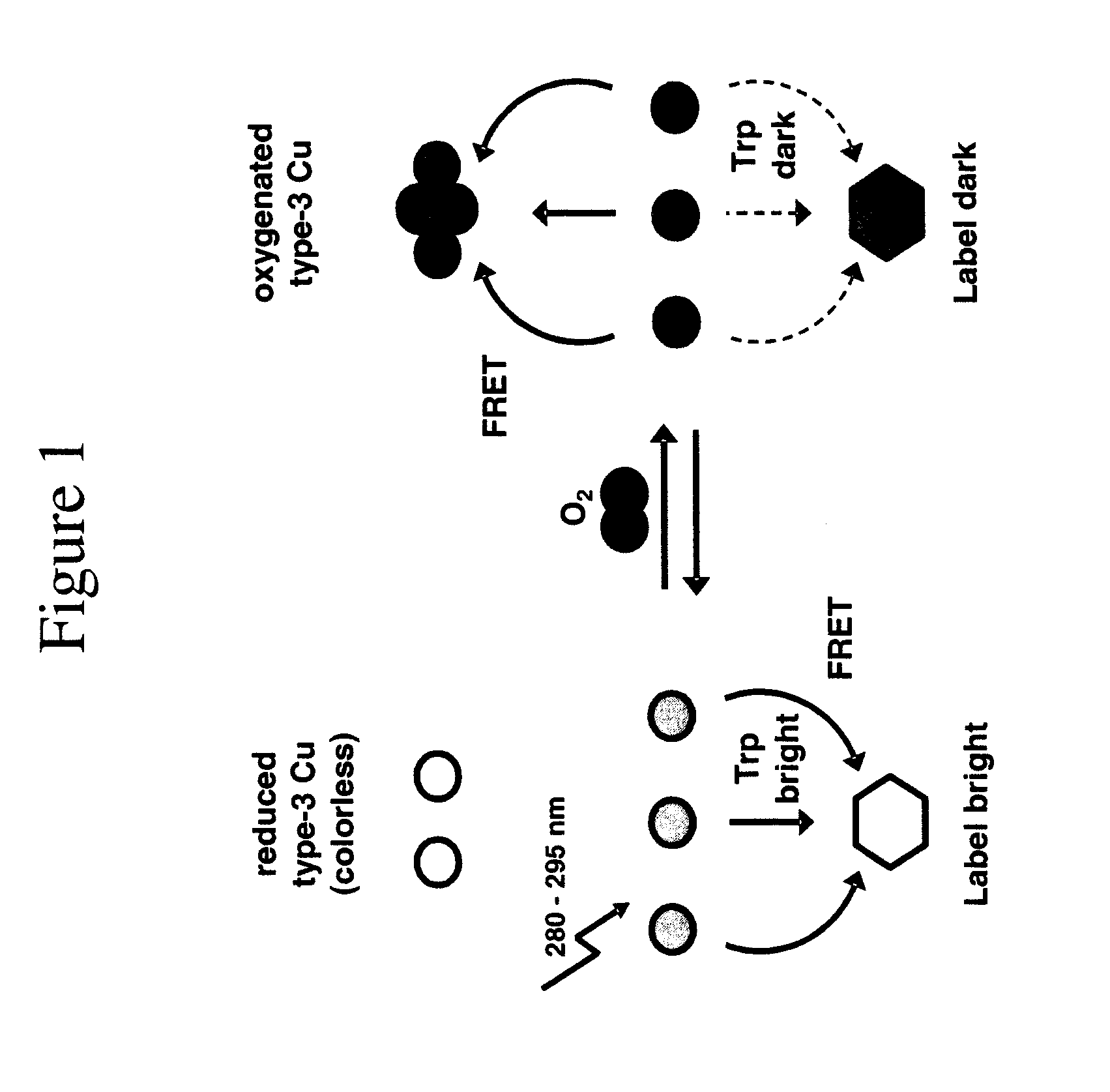
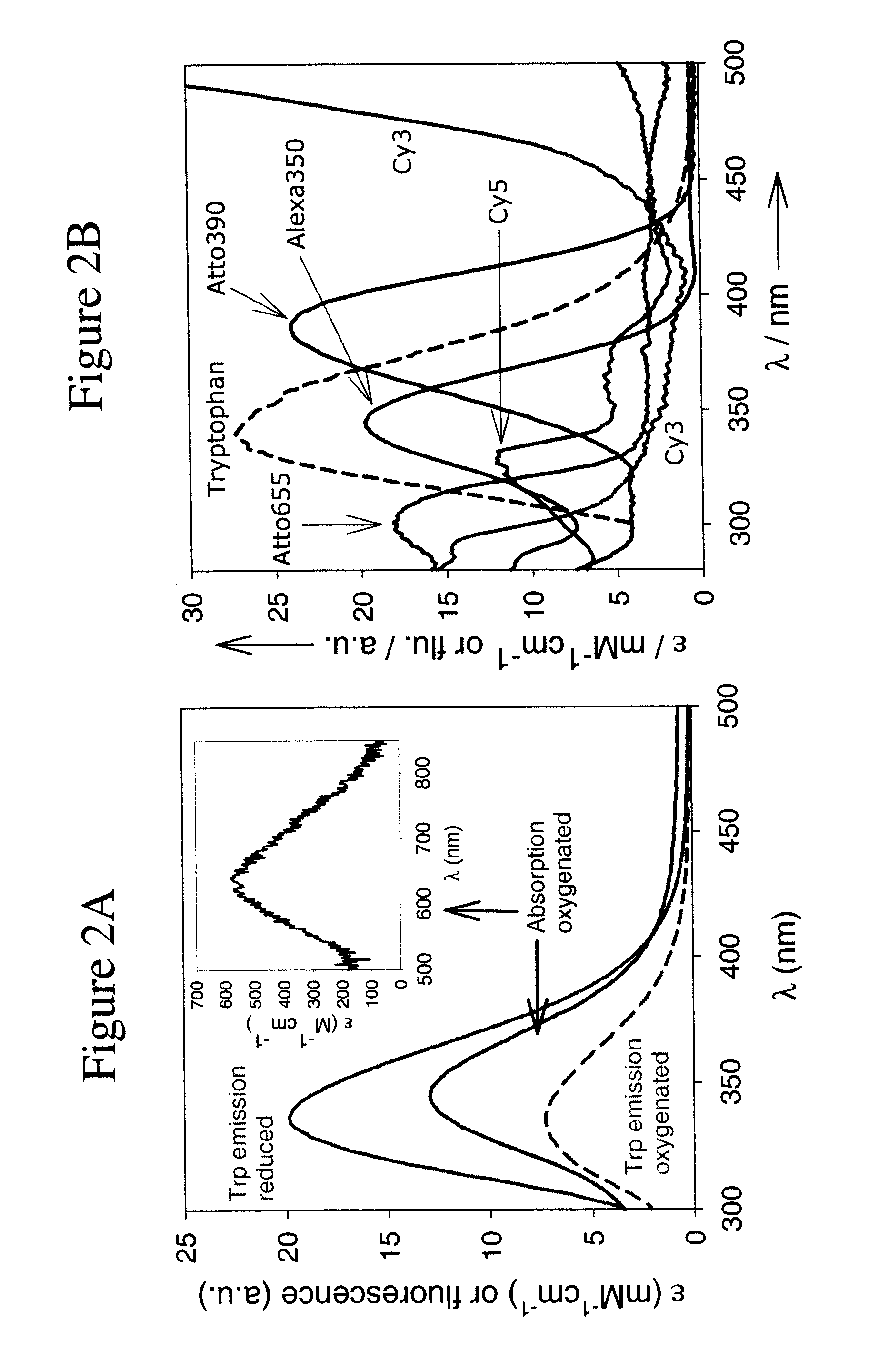
[0110]S.c. Ty contains 12 Trp residues on a total of 271 amino-acids (4.4% against ˜1% on average [10]), which cluster around the type-3 centre. The Trp fluorescence shows a maximum at 339 nm upon excitation at 280 nm. In an air-saturated solution (0.26 mM O2), practically all protein occurs in the oxygenated form (see FIG. 2A). Upon complete deoxygenation, the Trp fluorescence increases by a factor of 2.7 while the shape and position of the emission band remain unchanged. For the C.a. Hc samples, this factor, further referred to as the switching ratio SR (=Fred / Foxy), amounts to 2.2.

example 2

Dyes (Reference)

[0111]FIG. 2B shows absorption spectra between 250 and 500 nm of the five dyes selected for this study: Alexa350, Atto390, Cy3, Cy5 and Atto655, as well as their overlap with the Ty tryptophan emission. The excitation wavelength was 280 nm. Together these dyes emit at wavelengths spanning the whole visible spectrum (Table 2 and FIG. 2B). This allows the researcher to choose a dye which emits at a wavelength which does not interfere with other fluorescent systems in the sample.

TABLE 2Switching ratios, spectral overlap integrals and Förster radii forTrp and the dyes utilised in this study.Ro, TrpλemSR[a]SR[a]Jtrp Ty[b]Ty[c]Dyes(nm)TyrHc(nm4M−1 cm−1 × 10⁻¹³)(Å)Trp3392.72.213.023Alexa3504401.82.416.524Atto3904702.22.121.125Cy35662.82.25.920Cy56654.22.35.820Atto6556844.32.17.221[a]denotes the dye emission switching ratio (Fred / Foxy) observed with excitation at 280 nm.[b]Calculated spectral overlap integrals between the Trp emission and the absorption of the oxygenated pro...

example 3

Reference

O2 Binding and Label Fluorescence

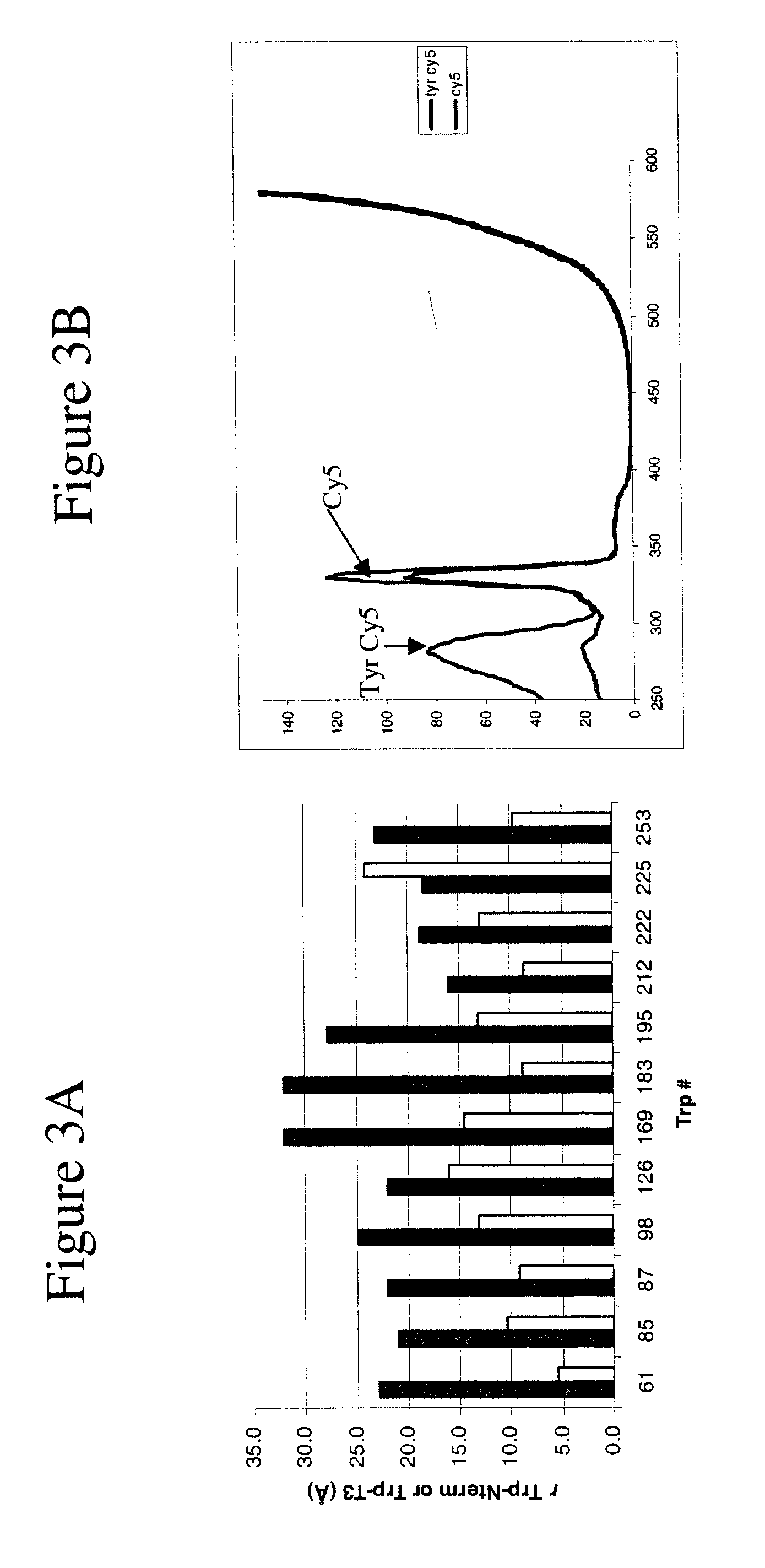
[0113]Excitation absorption spectrums were recorded in this Example using a monochromator in the detection path, that has its wavelength set at an emission band of the molecule to be studied, in this case 660 nm for Cy5. Excitation is achieved by using a white light source and employing a second monochromator between light source and sample. The wavelength of this monochromator was slowly scanned. When the wavelength of the excitation light matched an absorption band of Cy5, the dye started to fluoresce (at 660 nm) and the emitted light was observed in the detection set-up. By recording the fluorescence intensity as a function of the wavelength of the exciting light, the absorption spectrum was obtained.

[0114]Both Hc and Ty were labelled at their N-terminus with each of the five dyes [12]. When setting the detection wavelength at the dye emission maximum, the excitation spectra of the labelled proteins exhibit a strong peak at 280 nm, i.e., ...


PUM

PropertyMeasurementUnit
wavelengthaaaaaaaaaa

Abstract

The present invention concerns a method of detection of an analyte in which a protein capable of binding the analyte and comprising a fluorescent energy label and an energy acceptor moiety capable of accepting energy emitted by the label or protein by Forster energy transfer (FRET), is exposed to incident electromagnetic energy to excite the protein or label, and the fluorescent emission of the label is measured; characterised in that the protein is encapsulated in a biocompatible, optically transparent matrix which is permeable to the analyte, and in that the protein undergoes no substantial conformational change during the method; further characterised in that the energy acceptor moiety has a more active and less active state, which is determined by the presence of analyte, and the emission from the label is indicative of the presence of analyte. A biocompatible optically transparent matrix in which a protein capable of binding an analyte is also provided.

Description

STATEMENT OF THE INVENTION[0001]The present invention relates to methods of detection in which fluorescent emission from a labelled protein is measured. The protein is encapsulated in a biocompatible, optically transparent polymer matrix. The fluorescent emission can be related to the concentration of an analyte present. Typically, the analyte is oxygen.BACKGROUND TO THE INVENTION[0002]The mechanism underlying the present invention is fluorescent resonance energy transfer (FRET). FRET occurs between a donor and an acceptor moiety.[0003]FRET is based on a distance-dependent interaction between the electronic excited states of two dye molecules in which excitation is transferred from a donor molecule to an acceptor molecule without the emission of a photon. This process is known as Förster energy transfer. The efficiency of FRET is dependent on the inverse sixth power of intermolecular separation [1], making it useful over distances comparable with the dimensions of biological macromo...

Claims


Application Information

Patent Timeline
Patent Type & Authority Applications(United States)
IPC IPC(8): G01N33/573G01N33/00
CPCG01N2021/6441G01N33/542
Inventor CANTERS, GERARD W.ZAUNER, GERHILDTEPPER, ARMAND W. J. W.BUBACCO, LUIGIAARTSMA, THIJS
Owner UNIV DEGLI STUDI DI PADOVA
Why Eureka
Try Eureka