
Inverter-integrated electric compressor

Active Publication Date: 2010-01-28
MITSUBISHI HEAVY IND LTD
View PDF0 Cites 5 Cited by
  • Summary
  • Abstract
  • Description
  • Claims
  • Application Information

AI Technical Summary

Benefits of technology

[0009]As described above, by enclosing a gel material or a resin material in the inverter accommodating section, the electrical equipments constituting the inverter device can be electrically insulated and protected. At the same time, the entry of water drops and transmission of vibrations to the electrical equipments can be prevented, and durability and reliability for the use environment can be improved. However, with the above-described configuration, when the enclosed gel material and inner air inside the inverter accommodating section thermally expand due to a rise in the ambient temperature, the inner pressure of the inverter accommodating section increases, and repeated stress caused by the inner pressure applies a load to the cover member sealing the inverter accommodating section and the components of the inverter device. Therefore, the cover member seal may be broken, and the components of the inverter device may be damaged.

Problems solved by technology

However, with the above-described configuration, when the enclosed gel material and inner air inside the inverter accommodating section thermally expand due to a rise in the ambient temperature, the inner pressure of the inverter accommodating section increases, and repeated stress caused by the inner pressure applies a load to the cover member sealing the inverter accommodating section and the components of the inverter device.
Therefore, the cover member seal may be broken, and the components of the inverter device may be damaged.
However, it is not desirable to reduce the infill amount of the gel material because its effectiveness will also be reduced.
With a typical vent port, it is difficult to release the inner pressure and water vapor generated inside the inverter device while preventing water from entering from the outside.

Method used


Image

  • Inverter-integrated electric compressor
  • Inverter-integrated electric compressor
  • Inverter-integrated electric compressor

Examples


first embodiment

[0059]A first embodiment of the present invention will be described with reference to FIGS. 1 to 5.

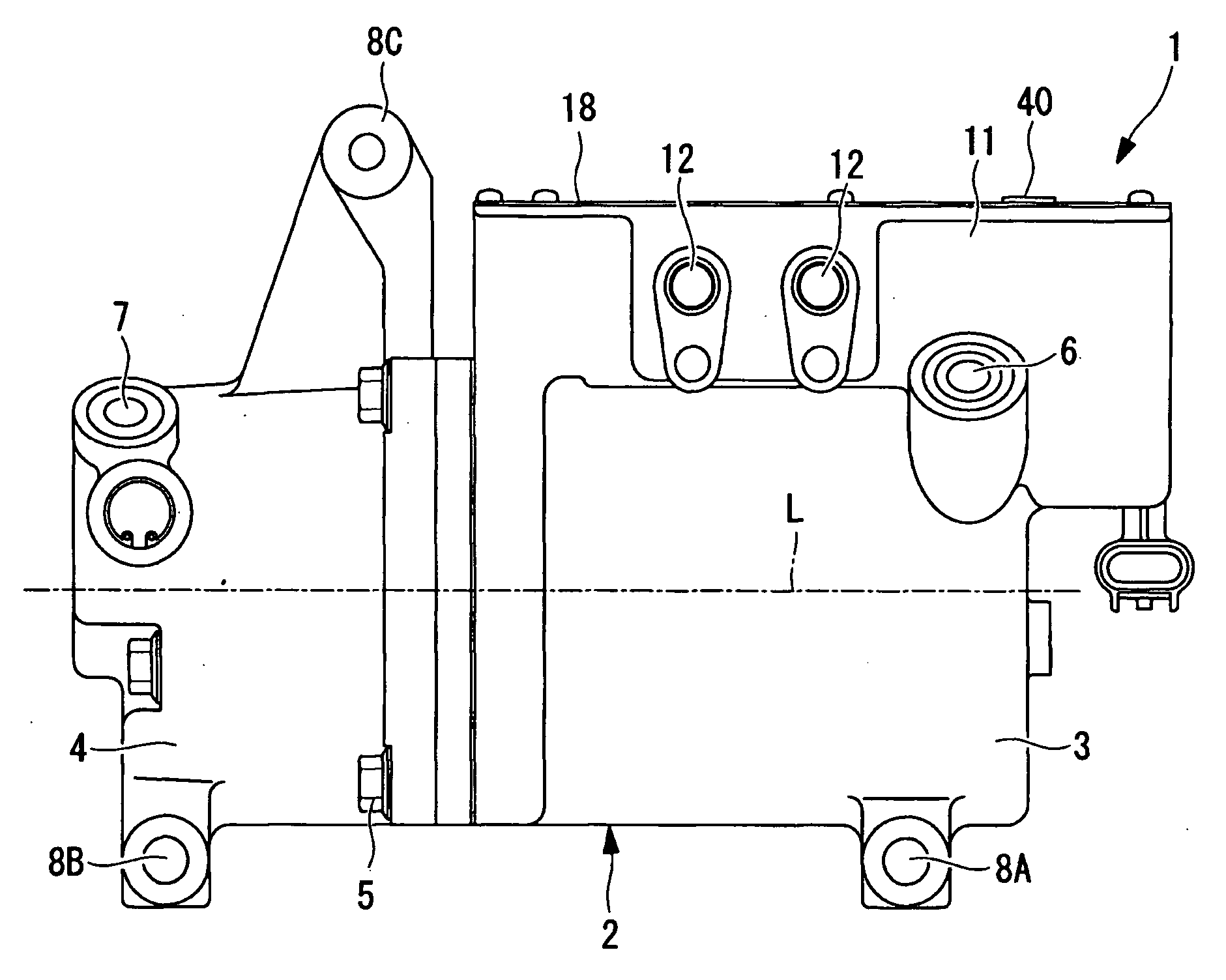
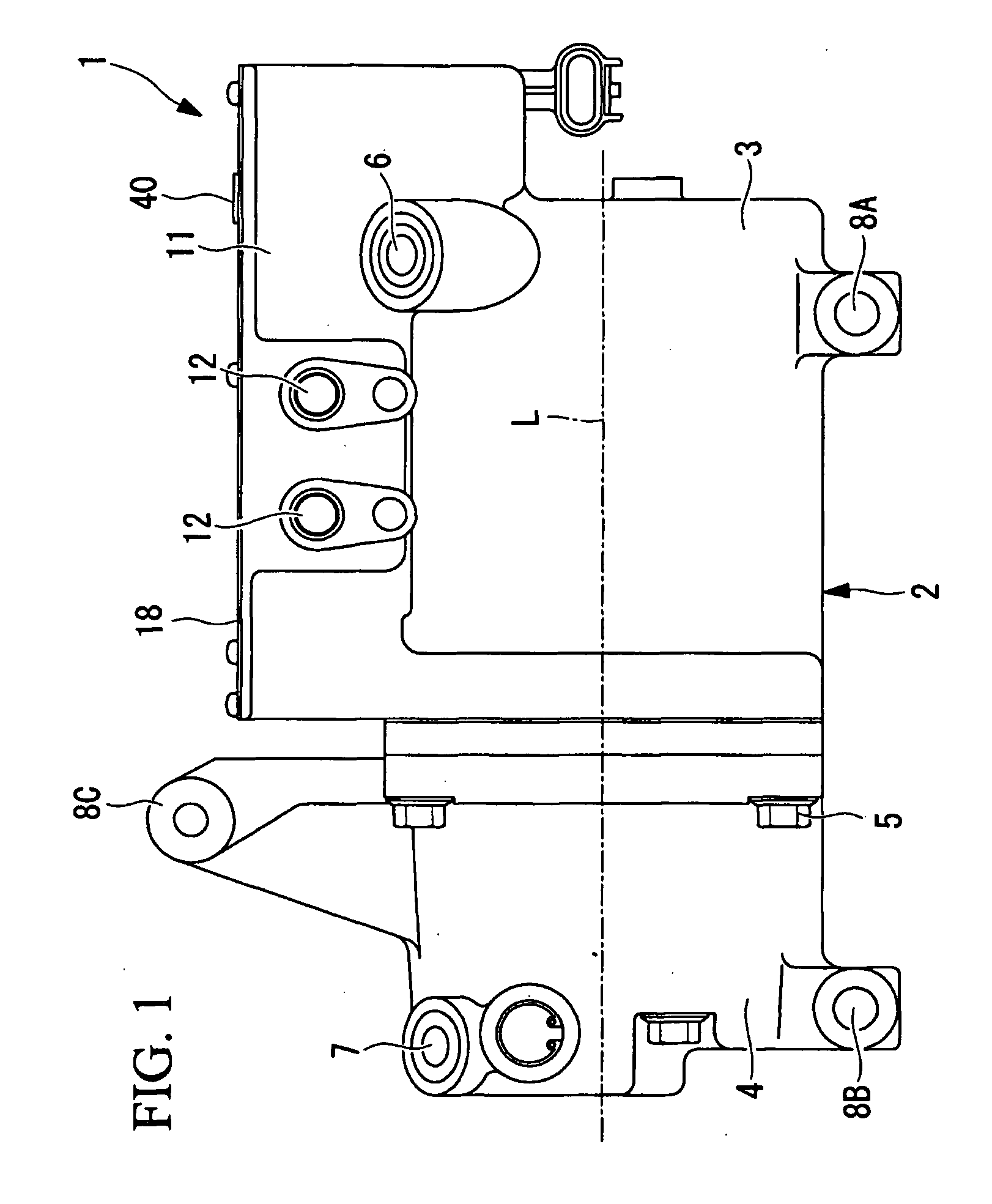
[0060]FIG. 1 is an external side view of an inverter-integrated electric compressor 1 according to the first embodiment of the present invention. The inverter-integrated electric compressor 1 includes a housing 2 constituting the outer casing thereof. The housing 2 is constructed by tightly securing a motor housing 3 accommodating an electric motor 9 (see FIG. 2) and a compressor housing 4 accommodating a compressing mechanism (not shown) with a bolt 5 to form an integrated unit. The motor housing 3 and the compressor housing 4 are formed by aluminum die-casting.

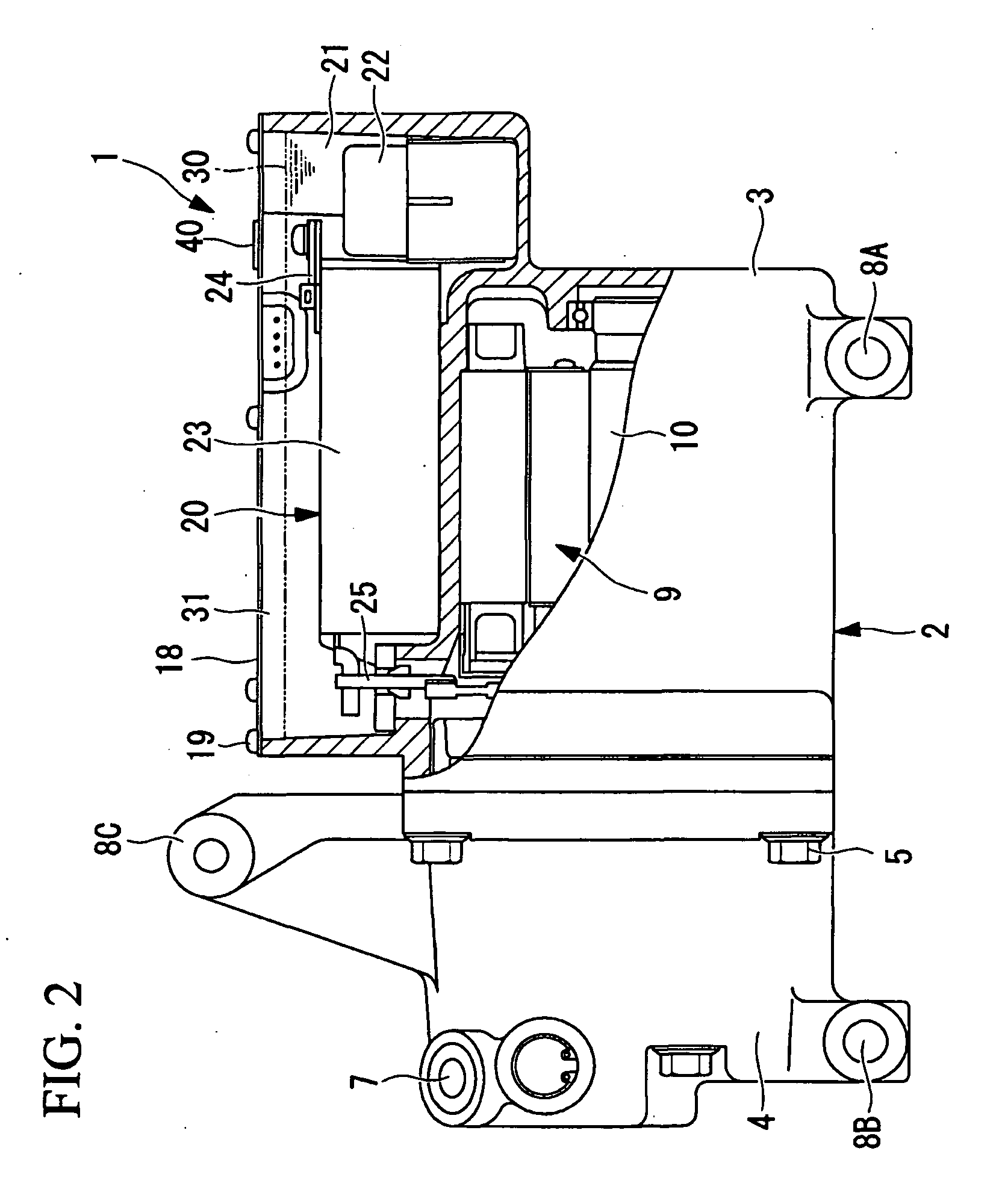
[0061]The electric motor 9 and the compressing mechanism (not shown) disposed inside the housing 2 are connected with a motor shaft 10 (see FIG. 2), and the compressing mechanism is driven by the rotation of the electric motor 9. A suction port 6 is provided at the rear end of the motor housing 3 (right side in FIG. 1). Low-pre...

second embodiment

[0078]Next, a second embodiment of the present invention will be described with reference to FIG. 6.

[0079]This embodiment differs from the above-described first embodiment in that a countermeasure against thermal expansion of the gel material 30 is provided for a structural component 50 mounted inside the inverter accommodating section 11. Since other aspects are the same as those according to the first embodiment, descriptions thereof are omitted.

[0080]As shown in FIG. 6, this embodiment provides the structural component 50 mounted inside the inverter accommodating section 11. In particular, the structural component 50 has an inner space 50A where the gel material 30 is enclosed and an air vent port 51 formed above the inner space 50A.

[0081]An example of the structural component 50 is a terminal block (structural component 50) mounted inside the inverter accommodating section 11. The terminal block is a resin block used for installing metal terminals inside the inverter accommodati...

third embodiment

[0083]A third embodiment of the present invention will be described with reference to FIGS. 7A and 7B.

[0084]The configuration of the cover member 18 of this embodiment differs from that of the above-described first embodiment. Since other aspects are the same as those according to the first embodiment, descriptions thereof are omitted.

[0085]As shown in FIGS. 7A and 7B, in this embodiment, the cover member 18 is constructed of a high-damping steel sheet 60. The high-damping steel sheet 60 may be selected from various types of high-damping steel sheets such as one constructed by sandwiching a rubber or resin layer 60B with a plurality of steel sheets 60A, as shown in FIG. 7A, or one constructed by coating one side or both sides of a steel sheet 60A with a rubber or resin layer 60B, as shown in FIG. 7B.

[0086]Even when the cover member 18 is constructed of the above-described high-damping steel sheet 60, the vent valve 40 may be formed in the same manner as in the first embodiment. In s...


PUM


Abstract

An inverter-integrated electric compressor that is capable of solving various problems caused by thermal expansion of a gel material filled inside an inverter accommodating section for vibration prevention and moisture prevention and capable of increasing reliability is provided. In the inverter-integrated electric compressor, an inverter accommodating section (11) is integrated with a periphery of a housing (2) accommodating an electric compressor; an inverter device (20) is accommodated inside the inverter accommodating section; a gel material (30) for vibration prevention and moisture prevention is filled in the upper section thereof so as to leave an air layer (31); an upper opening in the inverter accommodating section is sealed with a cover member (18); and a vent valve (40) formed of a moisture-permeable waterproof membrane (42) is provided in the cover member.

Description

TECHNICAL FIELD[0001]The present invention relates to an inverter-integrated electric compressor that is integrated with an inverter device suitable for use as an air conditioning compressor installed in a vehicle.BACKGROUND ART[0002]An inverter-integrated electric compressor has an inverter accommodating section (inverter box) integrated with the periphery of a housing, which accommodates an electric motor and a compressing mechanism. The inverter accommodating section accommodates an inverter device that converts DC power received from a power supply, such as a generator or a battery, into three-phase AC power and supplies it to the electric motor. The inverter device includes high-voltage components, such as a head capacitor or an inductor; a power board provided with a plurality of semiconductor power switching devices and a power-system controlling circuit that operates the semiconductor power switching devices; a CPU board on which is mounted a circuit having devices that oper...

Claims


Application Information

Patent Timeline
IPC IPC(8): F25B31/02B60H1/32F04B35/04
CPCF04B35/04
Inventor WATANABE, TAKAYUKISUZUKI, MANABUICHISE, YUKISAKAGUCHI, YUKIHIROHIRANO, TAKESHIYOSHIOKA, AKINORIHAGITA, TAKAYUKI
Owner MITSUBISHI HEAVY IND LTD
Features
  • Generate Ideas
  • Intellectual Property
  • Life Sciences
  • Materials
  • Tech Scout
  • Unparalleled Data Quality
  • Higher Quality Content
  • 60% Fewer Hallucinations
Learn More