
Polymer film, polarizing plate, and liquid crystal display

Inactive Publication Date: 2010-01-28
FUJIFILM CORP
View PDF2 Cites 9 Cited by
  • Summary
  • Abstract
  • Description
  • Claims
  • Application Information

AI Technical Summary

Benefits of technology

[0027]According to the invention, it is possible to provide a novel polymer film useful as an optically-compensatory film, and to provide a polarizing plate and a liquid-crystal display device comprising the film.
[0029]According to the invention, it is possible to provide the novel polymer film useful as an optically-compensatory film, which is suitable to continuous production.

Problems solved by technology

Heretofore, one serious defect of liquid-crystal display devices is that the viewing angle dependence of image display is large.
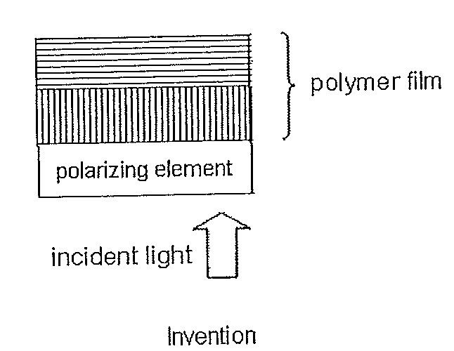
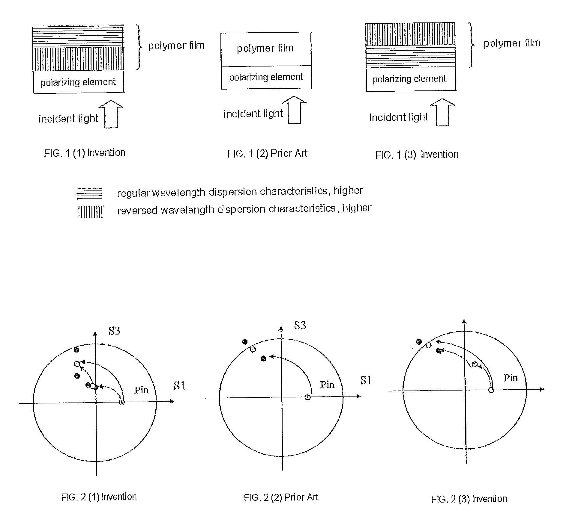
However, it is difficult to realize the contradictory properties of regular wavelength dispersion characteristics of retardation and reversed wavelength dispersion characteristics thereof in one film.
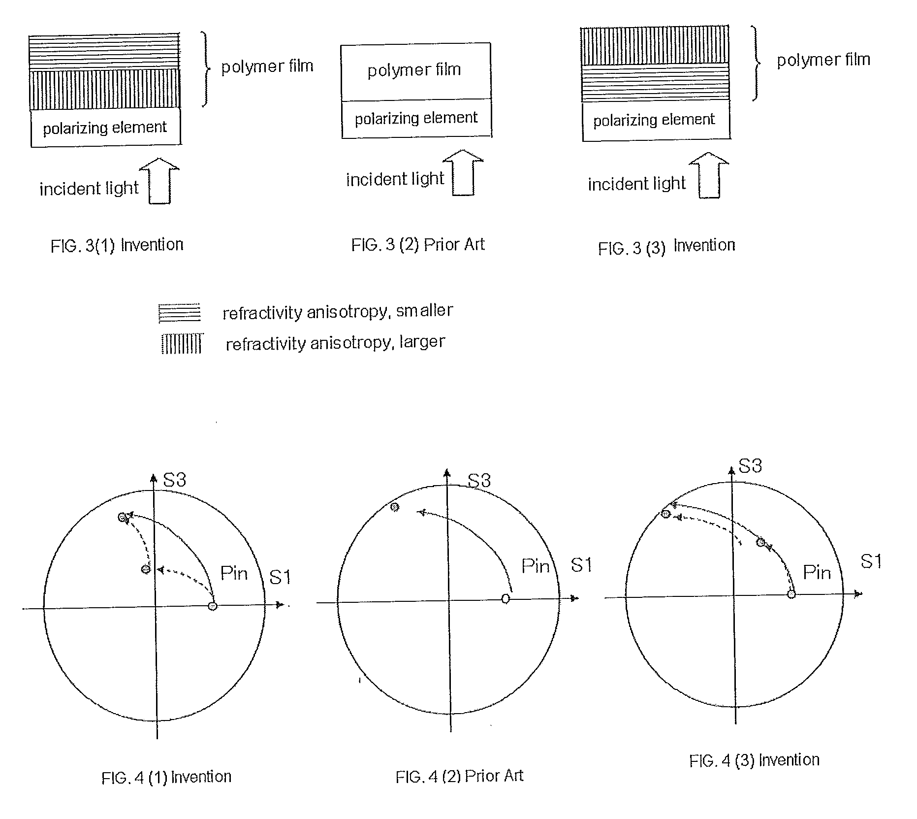
JP-A No. 2006-323152 proposes a transparent film of which the ratio of Re to Rth, Re / Rth varies in the direction of the thickness of the film, as an optically-compensatory film of liquid-crystal display devices, especially VA-mode liquid-crystal display devices; however, this does not illustrate a technology of changing the refractivity anisotropy (Δn=nx−ny) between the two surfaces of the film, and does not describe at all the wavelength dispersion characteristics of the refractivity anisotropy of the film.

Method used


Image

  • Polymer film, polarizing plate, and liquid crystal display
  • Polymer film, polarizing plate, and liquid crystal display
  • Polymer film, polarizing plate, and liquid crystal display

Examples


examples

[0130]The invention is described more concretely with reference to the following Examples, in which the material and the reagent used, their amount and their ratio, the details of the treatment and the treatment process may be suitably modified or changed not overstepping the sprit and the scope of the invention. Accordingly, the scope of the invention should not be limited by the following Examples.

1. Examples of Production of Polymer Film:

[0131]The constitutive ingredients were mixed in the ratio shown in Table 1 below, thereby preparing cellulose acylate solutions (dopes). Using a band caster, the cellulose acylate solution was cast. In Table 1, “TD” means a transverse direction. Drying:

[0132]In these Examples, the dope, after having cast on the surface of the band, was dried on the band under any of the following two different drying conditions for the purpose of making the produced film have a difference in the refractivity anisotropy between the two surfaces of the film.

(1) Dr...

examples of

2. Examples of Production of Polymer Film:

[0142]Polymer films were produced in the same manner as in “1. Examples of Production of Polymer Film”, which, however, were not stretched. The films were dried under the “drying condition 1”. The optical properties of the thus-produced polymer films were determined and shown in the following Table.

TABLE 3Film No.9PolymerCellulose acylate(2.86*1)Plasticizer (1)Triphenyl phosphate[amount*2][7%]Plasticizer (2)Biphenyl phosphate[amount*2][5%]Rev. Material*3—[amount*2]—Reg. Material*4Reg. Material No. 1[amount*2][7%]Re(446)[nm]−7Re(548)[nm]−5.9Re(629)[nm]−6.1Rth(446)[nm]111Rth(548)[nm]108Rth(629)[nm]106

3. Production of Polarizing Plate:

[0143]The surface of the polymer film produced in the above was saponified with alkali. Concretely, the film was dipped in an aqueous 1.5 N sodium hydroxide solution at 55° C. for 2 minutes, then washed in a water-washing bath at room temperature, and neutralized with 0.1 N sulfuric acid at 30° C. Again this was w...


PUM


Abstract

A polymer film stretched after formed by solution casting, of which the wavelength dispersion of the refractivity anisotropy and / or the refractivity anisotropy differ between two surfaces of the film is disclosed.

Description

CROSS-REFERENCE TO RELATED APPLICATIONS[0001]This application claims benefit of priority under 35 U.S.C. 119 to Japanese Patent Application No. 2008-190713 filed on Jul. 24, 2008, which is expressly incorporated herein by reference in its entirety.BACKGROUND OF THE INVENTION[0002]1. Technical Field[0003]The present invention relates to a polymer film useful as a component part of liquid-crystal display devices and the like, and to a polarizing plate and a liquid-crystal display device comprising the film.[0004]2. Background Art[0005]Applications of liquid-crystal display devices are expanding year by year as power-saving and space-saving image display devices. Heretofore, one serious defect of liquid-crystal display devices is that the viewing angle dependence of image display is large. However, VA-mode or IPS-mode, wide viewing angle liquid-crystal display devices have been put into practical use, and in that situation, the demand for liquid-crystal display devices is rapidly expan...

Claims


Application Information

Patent Timeline
IPC IPC(8): G02F1/1335G02B1/08
CPCG02B5/3033G02F1/13363G02F1/133528G02B5/3083
Inventor TOYAMA, HIROFUMIYASUDA, KOTAROINO, YUSUKEYANAI, YUJIROSASADA, YASUYUKITAKEDA, JUN
Owner FUJIFILM CORP
Learn More