2-dimensional image display device, illumination light source and exposure illumination device

a technology of illumination light source and exposure illumination, which is applied in the direction of instruments, color television details, projectors, etc., can solve the problems of generating speckle noise in the display device, complicating the optical system, and not being able to use a fixed wall surface as a screen, so as to achieve uniform illumination, effectively suppress speckle noise, and achieve uniform illumination

Active Publication Date: 2010-01-28
PANASONIC CORP
View PDF7 Cites 97 Cited by
  • Summary
  • Abstract
  • Description
  • Claims
  • Application Information

AI Technical Summary

Benefits of technology

[0015]In this illumination light source, uniform illumination can be obtained since the emission beam from the laser light source is scanned at least in the 1-dimensional direction. Further, since the emission beam scanned by the beam scan unit is diffused, the optical axis of the beam emerging from the light diffusion memb

Problems solved by technology

On the other hand, the above laser display device has a problem of so-called speckle noise that is generated due to the use of laser light sources having high coherency as light sources.
Thus, it is not possible to use a fixed wall surface as a screen and to suppress the speckle noise by an op

Method used


Image

  • 2-dimensional image display device, illumination light source and exposure illumination device
  • 2-dimensional image display device, illumination light source and exposure illumination device
  • 2-dimensional image display device, illumination light source and exposure illumination device

Examples


first embodiment

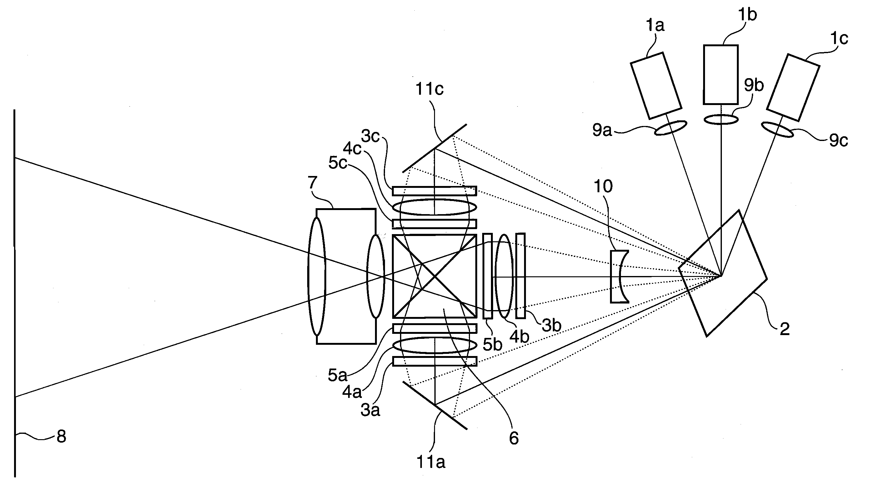
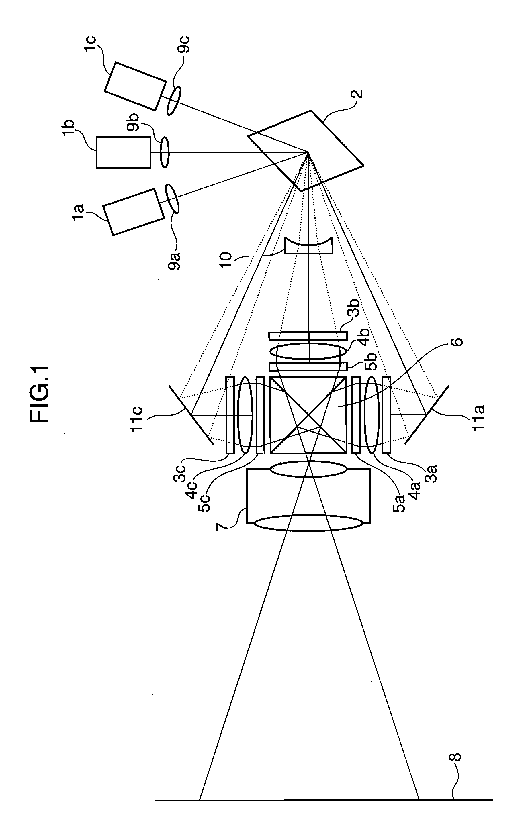
[0047]FIG. 1 is a schematic construction diagram of a 2-dimensional image display device according to a first embodiment of the present invention. Laser beams emitted from a red laser light source 1a, a green laser light source 1b and a blue laser light source 1c are substantially condensed by condenser lenses 9a, 9b and 9c, and reflected and two-dimensionally scanned by a 2-dimensional beam scan unit 2.

[0048]Gas lasers such as He—Ne lasers, He—Cd lasers or Ar lasers or semiconductor lasers such as AlGaInP semiconductor lasers or GaN semiconductor lasers or SHG lasers having solid-state lasers as fundamental waves can be used as the laser light sources 1a, 1b and 1c. A micromachine moving mirror using a semiconductor process, a combination of a galvanometer mirror and a polygon mirror or the like can be used as the 2-dimensional beam scan unit 2. It should be noted that the 2-dimensional beam scan unit 2 is not particularly limited to the reflection-type 2-dimensional beam scan unit...

second embodiment

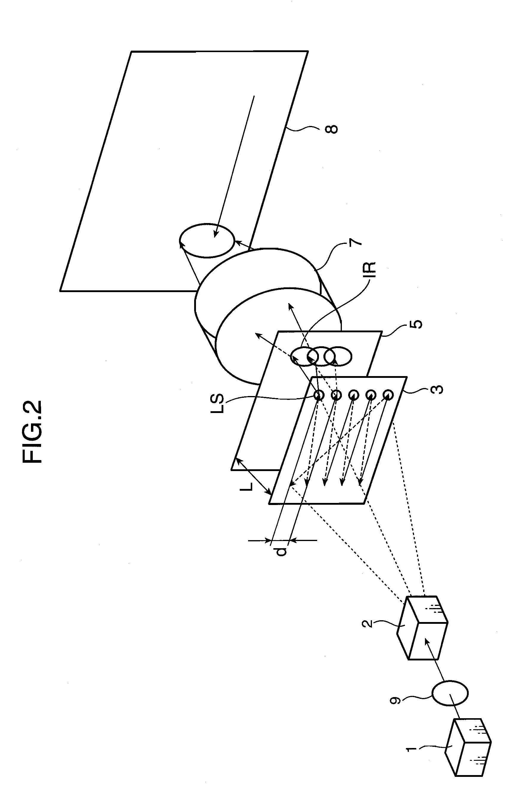
[0061]Next, a second embodiment of the present invention is described. FIG. 4 is a schematic construction diagram of an optical system for one color extracted from a 2-dimensional image display device according to the second embodiment of the present invention. Since the 2-dimensional image display device according to the second embodiment is the same as the one shown in FIG. 1 except the construction shown in FIG. 4, the same parts are neither shown nor described in detail.

[0062]In the second embodiment, instead of the 2-dimensional beam scan unit 2 shown in FIG. 2, a 1-dimensional beam splitting grating 12 and a 1-dimensional beam scan unit 15 are used as shown in FIG. 4. For example, a holographic optical element (HOE) or the like can be used as the 1-dimensional beam splitting grating 12, and a galvanometer mirror or the like can be used as the 1-dimensional beam scan unit 15.

[0063]In the above construction, after passing through a condenser lens 9, a light beam from a laser lig...

third embodiment

[0073]Next, a third embodiment of the present invention is described. FIG. 10 is a conceptual diagram of an optical system for one color extracted from a 2-dimensional image display device according to the third embodiment of the present invention. Since the 2-dimensional image display device according to the third embodiment is the same as the one shown in FIG. 1 except the construction shown in FIG. 10, the same parts are neither shown nor described in detail.

[0074]In the third embodiment, instead of the 2-dimensional beam scan unit 2 shown in FIG. 2, a 2-dimensional beam splitting grating 17 and a 2-dimensional fine angle beam scan unit 16 are used as shown in FIG. 10. In this construction, a light beam from a laser light source 1 is finely scanned in 2-dimensional directions in the 2-dimensional fine angle beam scan unit 16 and then incident on the 2-dimensional beam splitting grating 17 after passing through a condenser lens 9. The 2-dimensional beam splitting grating 17 is a d...


PUM


Abstract

A 2-dimensional beam scan unit (2) reflects emission beams from a red laser light source (1a), a green laser light source (1b) and a blue laser light source (1c) and scans in a 2-dimensional direction. Diffusion plates (3a, 3b, 3c) diffuse the respective light beams scanned in the 2-dimensional direction to introduce them to corresponding spatial light modulation elements (5a, 5b, 5c). The respective spatial light modulation elements (5a, 5b, 5c) modulate the respective lights in accordance with video signals of the respective colors. A dichroic prism (6) multiplexes the lights of the three colors after the modulation and introduces the multiplexed lights to a projection lens (7) so that a color image is displayed on a screen (8). Since the 2-dimensional light emitted from the beam scan unit is diffused to illuminate the spatial light modulation element, it is possible to change the optical axis of the beam emerging from the light diffusion member for irradiating the spatial light modulation element moment by moment, thereby effectively suppressing speckle noise.

Description

TECHNOLOGICAL FIELD[0001]The present invention relates to a 2-dimensional image display device, an illumination light source and an exposure illumination device and also to a video display device such as a video projector, a television receiver or a liquid crystal panel.BACKGROUND ART[0002]In recent years, laser display devices using laser light sources have attracted more attentions. Conventionally, color spectra of fluorescent materials are wide and only the subdued color can be obtained even upon displaying a single color in a television receiver using a cathode-ray tube. On the other hand, in a laser display device using laser light sources, it becomes possible to display a very vivid image having high color purity by using laser light sources having suitable wavelengths since lights from the respective light sources are monochromatic lights.[0003]FIG. 29 shows the schematic construction of a conventional laser display device. Lights from laser light sources 101a to 101c of RGB ...

Claims


Application Information

Patent Timeline
IPC IPC(8): G03B21/14
CPCG02B17/004G02B26/0808G02B27/0905G02B27/0933G02B27/0944H04N9/3161G02B27/1046G02B27/1093G02B27/145G02B27/149G03B21/14G02B27/102G03B21/2033G03B21/208G03B33/12
Inventor KASAZUMI, KENICHIKITAOKA, YASUOMIZUUCHI, KIMINORIYAMAMOTO, KAZUHISA
Owner PANASONIC CORP
Why Eureka
Try Eureka