Magnetic random access memory and write method of the same
a random access and memory technology, applied in the field of magnetic random access memory and write method of the same, can solve the problems of large write current, large hsw, and limit on miniaturization
- Summary
- Abstract
- Description
- Claims
- Application Information
AI Technical Summary
Benefits of technology
Problems solved by technology
Method used
Image

Examples
first embodiment
[0052]In the first embodiment of the present invention, in order to overcome the obstacle to realize a large-scale magnetic random access memory (MRAM) only through the cell size reduction technique, formed is a magnetoresistive effect element that stores data of three or more levels in a single cell using spin-transfer-magnetization-switching and two-terminal TMR structure.
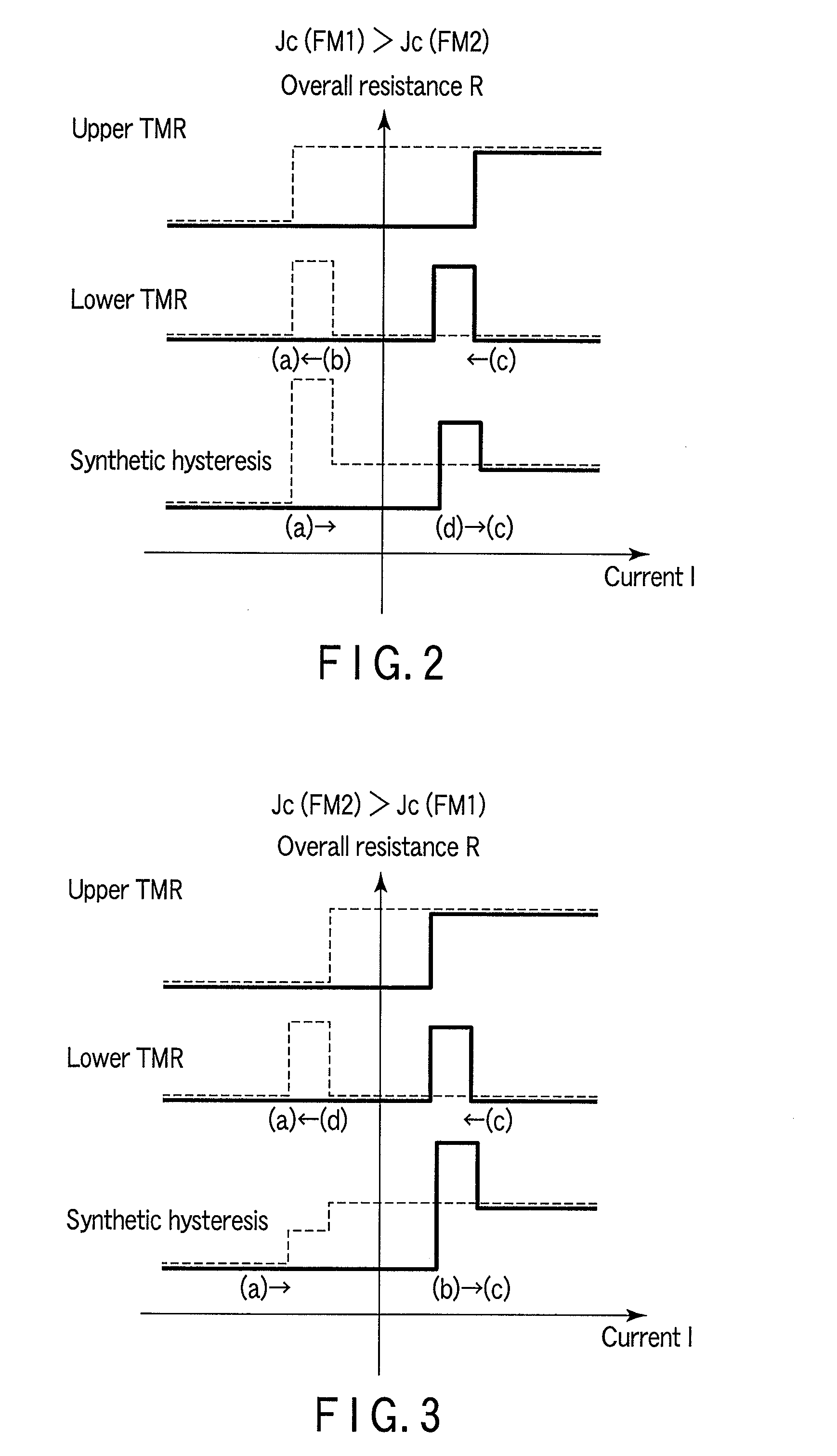
[0053]As indicated by equations 4 to 7 above, the switching current threshold for the spin transfer is determined by the damping constant α, the saturation magnetization Ms of the free layer, and the volume (V) of the free layer, or the thickness of the free layer, and the like. Accordingly, the switching current threshold can be appropriately designed by controlling the material, stacked structure, film thickness, and the like of the TMR structure.
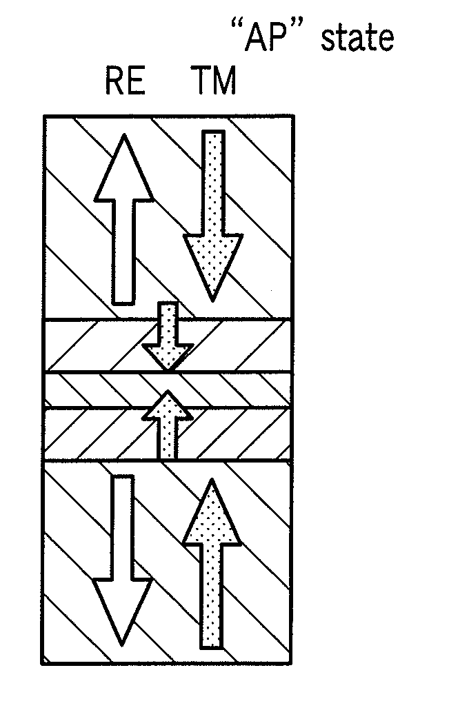
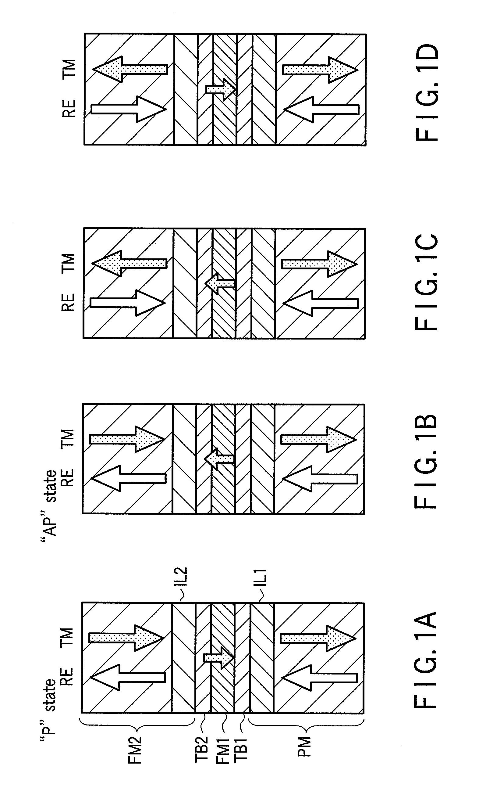
[0054]FIGS. 1A to 1D are schematic views for explaining an MRAM according to the first embodiment of the present invention, showing the configuration of a memory cell ...
second embodiment
[0086]FIGS. 6A to 6C schematically show an MRAM cell according to the second embodiment of the present invention. FIGS. 7A to 7C schematically show the hysteresis loops for the MRAM cell.
[0087]In the MRAM cell according to the second embodiment, one magnetic tunnel junction (a single magnetic tunnel junction) is used to provide the TMR effect. A pinned layer PM and free layer FM are each made of a ferrimagnetic material containing a rare-earth metal (RE) and transition metal (TM). Transition metal layers (interface layers) IL1 and IL2 are respectively formed in the pinned layer PM and free layer FM near a tunnel barrier TB. The tunnel barrier TB is sandwiched between the transition metal layers IL1 and IL2. The exchange coupling between the pinned layer PM and free layer FM makes the perpendicularly-magnetized parallel and antiparallel states of the TMR effect.
[0088]In the second embodiment, the exchange coupling between the transition metal layer IL2 and ferrimagnetic layer of the ...
third embodiment
[0101]FIGS. 10A to 10D schematically show an MRAM cell according to the third embodiment of the present invention. FIGS. 11A to 11D schematically show the hysteresis loops of the MRAM cell.
[0102]In the MRAM cell according to the third embodiment of the present invention, one magnetic tunnel junction is used to present the TMR effect as in the second embodiment. A pinned layer PM and free layer FM are each made of a ferrimagnetic material containing a rare-earth metal (RE) and transition metal (TM). Transition metal layers (interface layers) IL1 and IL2 are respectively formed in the pinned layer PM and free layer FM near a tunnel barrier TB. The tunnel barrier TB is sandwiched between the transition metal layers IL1 and IL2. The exchange coupling between the pinned layer PM and free layer FM produces perpendicularly-magnetized parallel and antiparallel states of the TMR effect.
[0103]The exchange coupling between the transition metal layer IL2 and the ferrimagnetic layer of the free ...
PUM
 Abstract
Description
Claims
Application Information
 - Generate Ideas
- Intellectual Property
- Life Sciences
- Materials
- Tech Scout
- Unparalleled Data Quality
- Higher Quality Content
- 60% Fewer Hallucinations
Browse by: Latest US Patents, China's latest patents, Technical Efficacy Thesaurus, Application Domain, Technology Topic, Popular Technical Reports.
© 2025 PatSnap. All rights reserved.Legal|Privacy policy|Modern Slavery Act Transparency Statement|Sitemap|About US| Contact US: help@patsnap.com