Apparatus, System and Method for Cascaded Power Conversion

a power converter and cascade technology, applied in the direction of electric variable regulation, process and machine control, instruments, etc., can solve the problems of limited power delivery, over-complexity of various led drivers, and low efficiency, and achieve the effects of more available and better component selection, constant current output, and long useful li

Active Publication Date: 2010-02-04
CHEMTRON RES
View PDF2 Cites 310 Cited by
  • Summary
  • Abstract
  • Description
  • Claims
  • Application Information

AI Technical Summary

Benefits of technology

[0013]The exemplary embodiments of the present invention provide numerous advantages for supplying power to loads such as LEDs. The various exemplary embodiments are capable of sustaining a plurality of types of control over such power delivery, such as providing a substantially constant current output. The exemplary embodiments may be provided which operate over a wide range of input voltages and with acceptable internal voltage stress levels, further providing for more available and better component selection and longer useful life for the selected components. The exemplary embodiments utilize a control method that provides for an accurate, stable output. The exemplary embodiments further provide a substantially close-to-unity power factor when connected to an AC line for input power, and further generate negligible harmonics and electromagnetic interference.

Problems solved by technology

For example, a capacitive drop off-line LED driver from On Semiconductor (Application Note AND8146 / D) is a non-isolated driver with low efficiency, is limited to delivering relatively low power, and at most can deliver a constant current to the LED with no temperature compensation, no dimming arrangements, and no voltage or current protection for the LED.
In general, these various LED drivers are overly complicated.
Some require control methods that are complex, some are difficult to design and implement, and others require many electronic components.
A large number of components can increase cost and reduce reliability.
Such current mode regulators require relatively many functional circuits, while nonetheless continuing to exhibit stability problems when used in the continuous current mode with a duty cycle or ratio over fifty percent.
While these prior art solutions addressed problems of instability, these hysteretic pulse train converters exhibited other difficulties, such as elevated electromagnetic interference, inability to meet other electromagnetic compatibility requirements, and relative inefficiency.
Other attempts, such as in U.S. Pat. No. 6,515,434 B1 and U.S. Pat. No.6,747,420, provide solutions outside the original power converter stages, adding additional feedback and other circuits, rendering the LED driver even larger and more complicated.
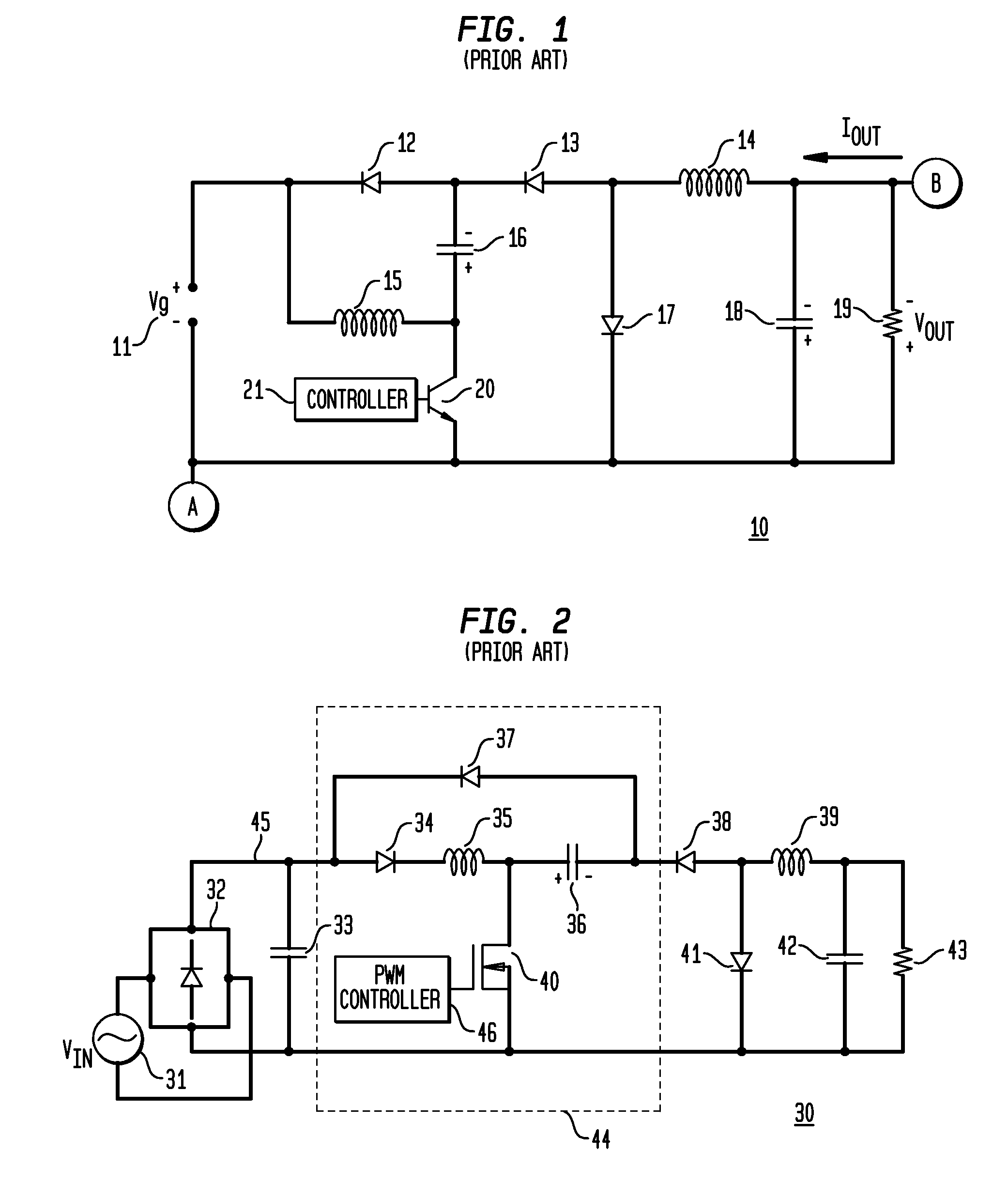
In order to reduce the component count, such converters may be constructed without isolation transformers by using two-stage converters with the second stage running at a very low duty cycle (equivalently referred to as a duty ratio), thereby limiting the maximum operating frequency, resulting in an increase in the size of the converter (due to the comparatively low operating frequency), and ultimately defeating the purpose of removing coupling transformers.
When these circuits are used as a current source, however, they become as inadequate as conventional one-stage converters, and exhibit even more problems when used with a sinusoidal input current.
For example, these circuits require a large capacitive filter following the rectified AC signal to continuously provide a steady DC output, thereby making power factor correction (“PFC”) practically impossible.
Also, currents in transistor 20 and the output load are flowing in opposite direction, creating a difficult topology for sensing operational signals and providing corresponding feedback signals (e.g., both nodes “A” and “B” are at return potentials).
Were this converter 10 to be used for current control in the output load, however, various issues may arise; for example, due to any imbalance of charges, voltages across capacitors 16 and 18 may not match, creating an excessive voltage across capacitor 16, which leads either to an over-design of the power stage or lower reliability, because this converter 10 cannot work if the voltage across capacitor 16 is greater than Vg.
Such floating operational signals make the provision of feedback signals to a controller extremely difficult, effectively requiring custom, application-specific controllers for power management.
Since power switches, capacitors, and other components may operate at high internal voltage levels, they may be subject to voltage stress, such as an electrical force or stress across a component that potentially may cause it to fail.
This prior art strategy, however, can cause voltage stress to increase dramatically over relevant portions of the input voltage range.
Switches that are able to handle such high voltage stress may be difficult to obtain, if available at all, or if they are available, they may be expensive or have other undesirable characteristics such as a slow switching response, a low gain, or a high on-resistance, any of which may serve to reduce conversion efficiency.
These voltage stress issues may cause engineers to avoid using or developing two-stage converters.

Method used


Image

  • Apparatus, System and Method for Cascaded Power Conversion
  • Apparatus, System and Method for Cascaded Power Conversion
  • Apparatus, System and Method for Cascaded Power Conversion

Examples


Embodiment Construction

[0050]While the present invention is susceptible of embodiment in many different forms, there are shown in the drawings and will be described herein in detail specific exemplary embodiments thereof, with the understanding that the present disclosure is to be considered as an exemplification of the principles of the invention and is not intended to limit the invention to the specific embodiments illustrated. In this respect, before explaining at least one embodiment consistent with the present invention in detail, it is to be understood that the invention is not limited in its application to the details of construction and to the arrangements of components set forth above and below, illustrated in the drawings, or as described in the examples. Methods and apparatuses consistent with the present invention are capable of other embodiments and of being practiced and carried out in various ways. Also, it is to be understood that the phraseology and terminology employed herein, as well as...


PUM


Abstract

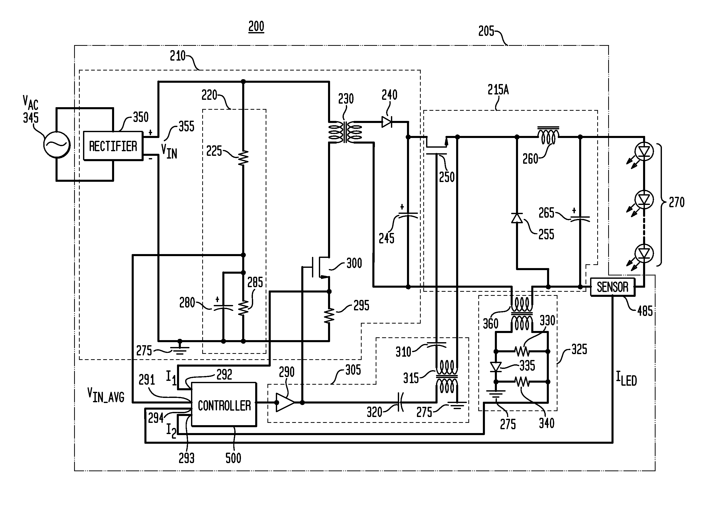
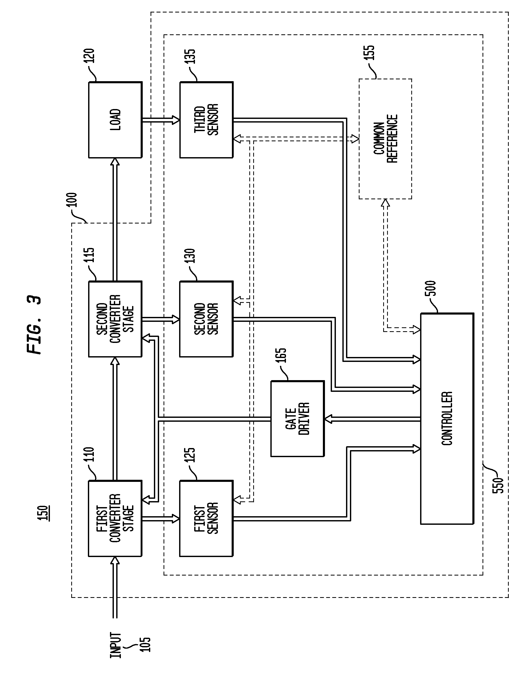
An apparatus, method and system are provided for power conversion to supply power to a load such as a plurality of light emitting diodes. An exemplary apparatus comprises: a first power converter stage having a first power switch and a first inductive element; a second power converter stage having a second power switch and a second inductive element; a plurality of sensors; and a controller. The second power converter stage provides an output current to the load. The controller is adapted to use a sensed input voltage to determine a switching period, and is further adapted to turn the first and second power switches into an on-state at a frequency substantially corresponding to the switching period while maintaining a switching duty cycle within a predetermined range.

Description

FIELD OF THE INVENTION[0001]The present invention in general is related to power conversion, and more specifically, to a system, apparatus and method for providing a two-stage, cascaded power converter for driving loads such as light emitting diodes (“LEDs”).BACKGROUND OF THE INVENTION[0002]A wide variety of off-line LED drivers are known. For example, a capacitive drop off-line LED driver from On Semiconductor (Application Note AND8146 / D) is a non-isolated driver with low efficiency, is limited to delivering relatively low power, and at most can deliver a constant current to the LED with no temperature compensation, no dimming arrangements, and no voltage or current protection for the LED.[0003]Other isolated off-line LED drivers also have wide-ranging characteristics, such as a line frequency transformer and current regulator (On Semiconductor Application Note AND 8137 / D); a current mode controller (On Semiconductor Application Note AND8136 / D); a white LED luminary light control s...

Claims


Application Information

Patent Timeline
Patent Type & Authority Applications(United States)
IPC IPC(8): H05B37/02H05B44/00
CPCH05B33/0815H05B37/02H02M3/33507H05B45/38H05B45/375H05B45/3725H05B45/385H05B47/165H05B44/00
Inventor SHTEYNBERG, ANATOLYRODRIGUEZ, HARRYLEHMAN, BRADLEY M.
Owner CHEMTRON RES
Why Eureka
Try Eureka